Last Updated on 13th April 2024 by peppe8o
In this tutorial I’m going to show you how to setup and wire a 8×8 Led Matrix with Raspberry PI and Python, explaining code.
A very simple electronic component, 8×8 Led Matrix with Raspberry PI (and Python) can display nice and simple images whose application limit is only your fantasy.
How 8×8 LED Matrix Works
8×8 LED matrix is a small display composed of 8 LED row, each one including 8 LEDs, thus forming a LED matrix (as per its name) . All its LED are usually monochromatic (only 1 colour). It appears as in following picture:
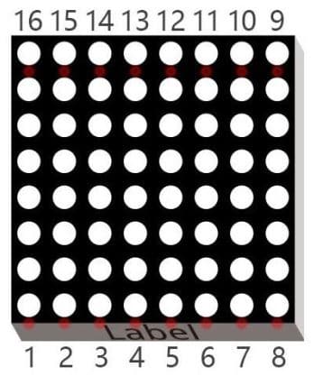
8×8 LED Matrix has 2 row of PINs in its back side. The lower one (near side label) are usually referred to from 1 to 8. The upper ones, on the other hand, are from 9 to 16 but in reverse sense, as shown in previous picture.
Positive pole of LEDs in each row and negative pole of LEDs in each column are connected together to create a matrix module. In this configuration, we have a “common anode” LED Matrix. There is a second type, where negative pole of LEDs in each row and positive pole of LEDs in each column are connected, This second type is called “common cathode”.
In this project I’m going to use a common anode LEDMatrix, but the following code should work also with a common cathode by inverting LED logic.
Following picture shows internal circuit og both common anode and common cathode models:
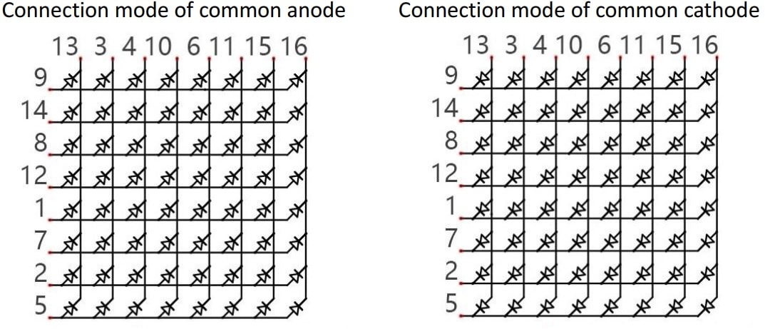
Please note in previous images that, differently from what one could think, pin rows physically close doesn’t represent columns or rows. PINs are mixed in a quite confusing way and you have to pay attention to cabling to connect in right way, otherwise you will get an unpredictable output.
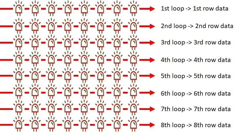
8×8 LED matrix can be powered and controlled both column by column or row by row. In this tutorial I’m going to setup a python code which scans row by row your display, as it simplify creating LED masks to show.
Our script will work with the following logic. A loop is set to iteratively scan 8×8 LED matrix, so that each loop run will select a specific row and put on/off LEDs of that row. Repeating this loop with a very high speed, it will appear to the human eye as a defined and continuous image, instead of a row scan, because of the principle of persistence already used also in my previous 4 digit-7 Segment display tutorial.
Please note that LED row data matches columns configuration.
As my matrix is a common anode, to get a LED on I will have to put its row selector to 1 and column selector to 0 (zero).
Last but not least, as you can see a 8×8 LED matrix requires 16 PINS, which can occupy a high number of GPIO ports from our Raspberry PI. To solve this problem, I’ve adopted for this project the use of 2 cheap 74HC595 shift register.
Finally, I will use a Raspberry PI Zero W for my project, but this guide works also with other Raspberry PI computer boards.
What We Need
As usual, I suggest adding from now to your favourite e-commerce shopping cart all the needed hardware, so that at the end you will be able to evaluate overall costs and decide if to continue with the project or remove them from the shopping cart. So, hardware will be only:
- Raspberry PI Zero W (including proper power supply or using a smartphone micro usb charger with at least 3A) or newer Raspberry PI Board
- high speed micro SD card (at least 16 GB, at least class 10)
- 8×8 LED Matrix
- 2x 74HC595 shift register
- dupont wiring
- resistors (8x 220 Ohm)
- (optional) breadboard
Check hardware prices with following links:


Wiring Diagram
Please find below my wiring diagram:
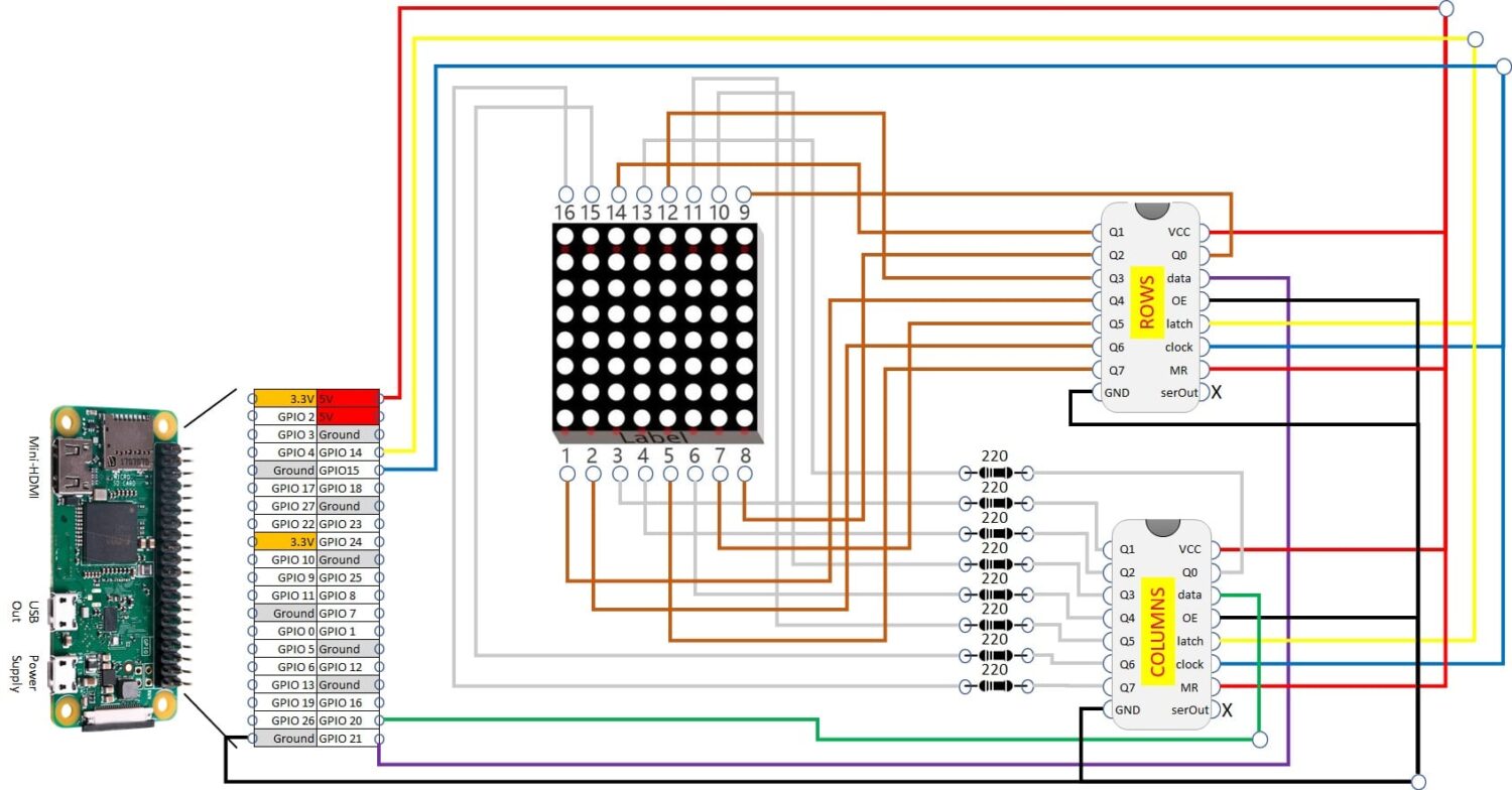
I’ve named shift registers to distinguish between the one which drives columns and the other which works for rows. Please note that latch from both shift registers goes together on same Raspberry PI PIN. Same for clock. Vcc from both shift registers are connected to Raspberry PI’s 5V PIN. More details can be found in my Using 74hc595 Shift Register with Raspberry PI tutorial.
As it can be a little complicated to wire from an optimized image inside a post, please find full definition image at https://peppe8o.com/wp-content/uploads/2021/05/Raspberry-PI-8×8-led-matrix-wiring-diagram.jpg.
Next table also helps in understanding connections:
| Shift Register | Sh.Reg port | Connects to | PIN |
|---|---|---|---|
| Column | C0 | 8×8 Matrix | 13 |
| Column | C1 | 8×8 Matrix | 3 |
| Column | C2 | 8×8 Matrix | 4 |
| Column | C3 | 8×8 Matrix | 10 |
| Column | C4 | 8×8 Matrix | 6 |
| Column | C5 | 8×8 Matrix | 11 |
| Column | C6 | 8×8 Matrix | 15 |
| Column | C7 | 8×8 Matrix | 16 |
| Column | Latch | Raspb.PI | GPIO 14 |
| Column | Clock | Raspb.PI | GPIO 15 |
| Column | Data | Raspb.PI | GPIO 20 |
| Row | R0 | 8×8 Matrix | 9 |
| Row | R1 | 8×8 Matrix | 14 |
| Row | R2 | 8×8 Matrix | 8 |
| Row | R3 | 8×8 Matrix | 12 |
| Row | R4 | 8×8 Matrix | 1 |
| Row | R5 | 8×8 Matrix | 7 |
| Row | R6 | 8×8 Matrix | 2 |
| Row | R7 | 8×8 Matrix | 5 |
| Row | Latch | Raspb.PI | GPIO 14 |
| Row | Clock | Raspb.PI | GPIO 15 |
| Row | Data | Raspb.PI | GPIO 21 |
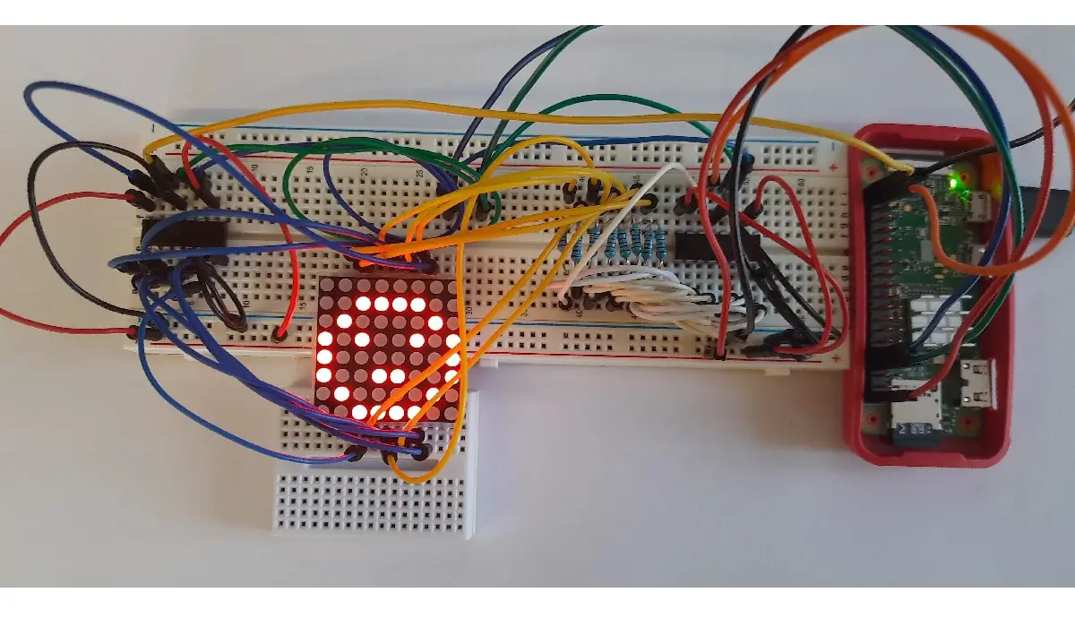
Following pictures show my RPI connected and working:
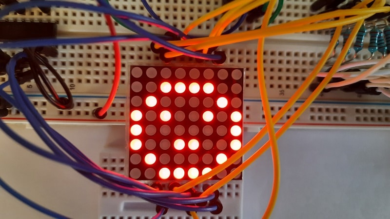
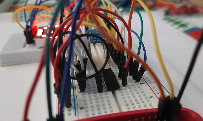
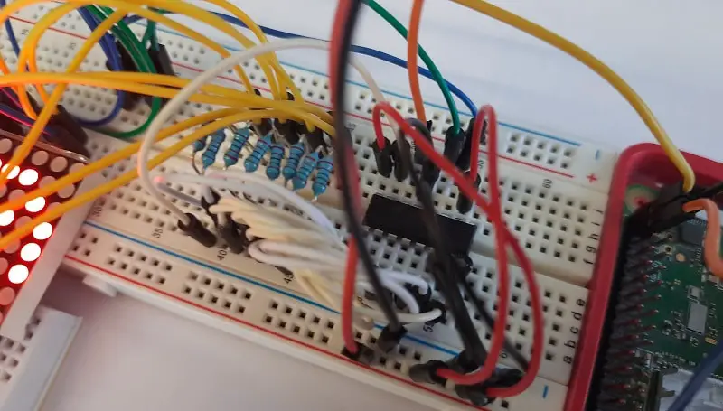
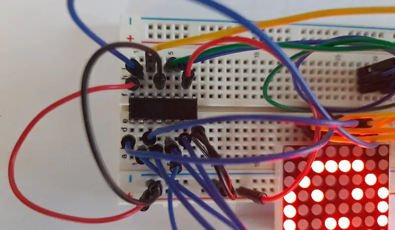
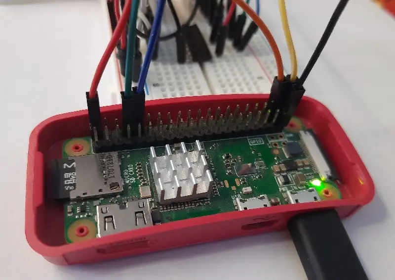
… I know, cabling could be better organized… 🙁
As you can see from pictures, I had to use a second expansion breadboard. This was because I was becoming crazy to make cabling correct, but you can also use breadboard only for shift registers and resistors, using cables directly to LED matrix.
Step-by-Step Procedure
Prepare Operating System
Start preparing your Raspberry PI operating system. You can install Raspberry PI OS Lite (for a headless, fast OS) or Raspberry PI OS Desktop (in this case using its internal terminal).
Make your OS updated:
sudo apt update -y && sudo apt upgrade -yRPI.GPIO should be already installed (otherwise, you can get it installed with the command “sudo apt install python3-rpi.gpio”).
Prepare 8×8 Led Matrix Script for Python
You can get my script directly in your Raspberry PI with the built-in wget, issuing following terminal command:
wget https://peppe8o.com/download/python/8x8LedDisplay.pyBelow my script description.
As common for python scripts, required modules are imported first:
import RPi.GPIO as GPIO
import sys
Then used Raspberry PI PINs are associated to variables for better management
columnDataPin = 20
rowDataPin = 21
latchPIN = 14
clockPIN = 15
As we use 2 shift registers, latch and clock will work together on same pins, while data PIN will be one for each shift register.
PIN naming is set to BroadCom (BCM) and all PINs are set to output mode:
GPIO.setmode(GPIO.BCM)
GPIO.setup((columnDataPin,rowDataPin,latchPIN,clockPIN),GPIO.OUT)
A Shift function is now defined. This function works as the one from Using 74hc595 Shift Register with Raspberry PI tutorial, with the difference that this sends data to 2 shift registers at the same time.
def shift_update_matrix(input_Col,Column_PIN,input_Row,Row_PIN,clock,latch):
GPIO.output(clock,0)
GPIO.output(latch,0)
GPIO.output(clock,1)
for i in range(7, -1, -1):
GPIO.output(clock,0)
GPIO.output(Column_PIN, int(input_Col[i]))
GPIO.output(Row_PIN, int(input_Row[i]))
GPIO.output(clock,1)
GPIO.output(clock,0)
GPIO.output(latch,1)
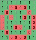
GPIO.output(clock,1)Now a LED map is required. Following “smile” variable is a list that has other lists as its elements. Each internal list represents a row. All rows will be sent to 8×8 LED Matrix, with “0” meaning a powered on LED, while “1” will represent a powered off LED:
smile=[["11111111"],\
       ["11000011"],\
       ["10111101"],\
       ["01011010"],\
       ["01111110"],\
       ["01100110"],\
       ["10111101"],\
       ["11000011"]]
You can better identify a smile from this variable in following alternative representation, where red (“0”) bits will be on and green (“1”) bits will be off:
From here the main loop starts with a while statement, followed by a “try”.
The RowSelect variable is initialized. This variable selects within the Row shift register what row to configure. So [1,0,0,0,0,0,0,0] will make 1rst row active from LED Matrix, then passing row data which will set what LEDs in the first row have to be on. [0,1,0,0,0,0,0,0] will select the second row, [0,0,1,0,0,0,0,0] the third and so on.
while True:
  try:
    RowSelect=[1,0,0,0,0,0,0,0]
A for loop is then used. Note that a range(0,8) doesn’t include the last value (8), so “i” will have values from 0 to 7. This loop send data to drive both shift registers with the previous function. In this execution, we are going to send “smile” variable to be displayed, but you can configure to show whatever you want, defining your image variable before the main loop:
    for i in range(0,8): # last value in rage is not included by default
      shift_update_matrix(''.join(map(str, smile[i])),columnDataPin,\
                          ''.join(map(str, RowSelect)),rowDataPin,clockPIN,latchPIN)
Then we use the well known, built-in slicing function from python to implement a list rotation:
RowSelect = RowSelect[-1:] + RowSelect[:-1]Finally, the “except KeyboardInterrupt:” statement intercepts interrupt key combination from user (CTRL+C from keyboard) to clean GPIO state before exiting the script:
  except KeyboardInterrupt:
    GPIO.cleanup()
    sys.exit()
Run the 8x8LedMatrix Python Script
To un this script and activate 8×8 LED matrix, simply use following terminal command:
python3 8x8LedDisplay.pyYour image will start appearing in your display. Stop the script by using CTRL+C.
Enjoy!

Open source and Raspberry PI lover, writes tutorials for beginners since 2019. He's an ICT expert, with a strong experience in supporting medium to big companies and public administrations to manage their ICT infrastructures. He's supporting the Italian public administration in digital transformation projects.
![]()
![]()
![]()
![]()
![]()
![]()
![]()