

Last Updated on 7th June 2025 by peppe8o
In this guide, I’ll show you how to connect and configure a 7-segment display with a Raspberry Pi computer board. I will show you how to connect and how to use it with Python.
This tutorial will cover both single digit 7-segment and 4-digit 7-segment displays.
About 7-segment Displays
A 7-segment display is a simple electronic display composed of 7 (surprise) LED segments. It is common to find an additional LED for a little dot near the classic 7 LED segments which compose a number. It runs in a very simple way with Raspberry PI GPIOs and Python coding.
There are 2 main kinds of these displays: single-digit and 4-digit.

Single-Digit 7-Segment Display
This device allows you to show only 1 digit, composing it by powering on one or more segments.
This 7-segment display is used in a wide range of applications, usually to display a single number. These devices have a simple internal wiring diagram, which maps one by one the LEDs to their pins:

By powering on one of the PINs, you will be able to power on the related segment as shown in the previous picture.
4-Digit 7-Segment Display
The 4-digit 7-segment display is still a simple electronic module, similar to the single display, but composed of 4 digits which can show at the same time 4 characters. It also has dot LEDs, but in different configurations (single for each digit, central colon, etc).
The 4-digit 7-segment display is widely known and used in digital clocks, simple screens and low-cost number displaying systems. It is used within a wide range of applications, usually to display time.
To show all the digits, as you can drive one digit at a time, you must drive each digit at a speed so that a human eye cannot perceive power off moments: this principle is based on the persistence of vision principle and is at the base of this device.
When using a 4-digit 7-segment display, please check if it is a common anode: the common anode pin connects to the power source. If it is a common cathode, the common cathode pin connects to the GND. This guide is based on cathode one, but the anode version works with the same code by inverting the digit selection logic.
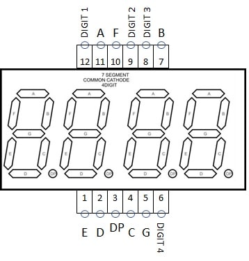
These devices have a simple internal wiring diagram:

As shown in the picture, once you configure the A, B, C, D, E, F, G, DP pins to 1 (HIGH) or 0 (LOW) to display the correct number in one digit, with anode displays the PINs 12, 9, 8 and 6 will drive it to the selected digit position by setting one of these to 1 (HIGH) and the other to 0 (LOW). For cathode elements, these four pins must all stay at 1 (HIGH) except for the digit you want to select by moving to 0 (LOW) its selector.
The following picture also shows the pinout for the cathodic 4-digit display I’m going to use:
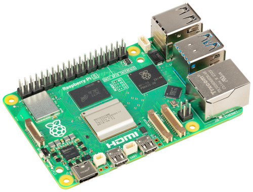
In this article, I’ll control the 7-Segment Display and the 4-digit 7-segment displays from a Raspberry PI 5 model B, but the following procedures will also apply to the other Raspberry PI computer boards.
What We Need
As usual, I suggest adding from now to your favourite e-commerce shopping cart all the needed hardware, so that at the end you will be able to evaluate overall costs and decide if to continue with the project or remove them from the shopping cart. So, hardware will be only:
- Raspberry PI Computer Board (including proper power supply or using a smartphone micro USB charger with at least 3A)
- high speed micro SD card (at least 16 GB, at least class 10)
- Dupont wirings
- Breadboard (optional)
- resistors (220 Ohm used)
- 7-segment display or 4-digit 7-segment display
Step-by-Step Procedures
You will find in the following chapters both the procedure for the 1-digit 7-segment display and the 4-digit 7-segment display. For the second, please go directly to the related chapter after installing the Raspberry PI OS.
Install Raspberry PI OS Operating System
The first step is installing the Raspberry PI OS Lite to get a fast and light operating system (headless). In this case, you will need to work from a remote SSH terminal. If you need a desktop environment, you can also use the Raspberry PI OS Desktop, in this case working from its terminal app. Please find the differences between the 2 OS versions in my Raspberry PI OS Lite vs Desktop article.
Make sure that your system is up to date. Connect via SSH terminal and type the following command:
sudo apt update -y && sudo apt full-upgrade -yControl a 7-segment Display from Raspberry PI Computer Board
Wiring Diagram
Prepare cabling according to the following wiring diagram, according to the Raspberry PI Pinout:

This wiring produces the following mapping between the display and the Raspberry PI:
| Display Segment | Display Pin | Raspberry PI GPIO |
|---|---|---|
| A | 7 | 14 (with 220 Ohm resistor) |
| B | 6 | 15 (with 220 Ohm resistor) |
| C | 4 | 18 (with 220 Ohm resistor) |
| D | 2 | 23 (with 220 Ohm resistor) |
| E | 1 | 24 (with 220 Ohm resistor) |
| F | 9 | 25 (with 220 Ohm resistor) |
| G | 10 | 8 (with 220 Ohm resistor) |
| DP | 5 | 7 (with 220 Ohm resistor) |
| GRD | 3 | GRD |
| GRD | 8 | GRD |
So, each Raspberry PI pin / GPIO powers on/off its related segment. Powering on the appropriate segments together will display the number we want to show.
Please find below some pictures from my cabling:


Get the p8o-pi Library and the 7-Segment Test Script
Please download the p8o-pi library from my download area to your Raspberry PI:
wget https://peppe8o.com/download/python/p8o_pi.pyAlternatively, you can also download the same library from my GitHub repository:
wget https://raw.githubusercontent.com/peppe8o/p8o_pi/refs/heads/main/p8o_pi.pyNow, you can download the test script from my download area:
wget https://peppe8o.com/download/python/7_segment/7segment-test.pyPlease note that the p8o_pi.py library must be in the same folder as the test script or in the Python libraries folder.
You can test your display by running the following command:
python 7segment-test.pyseven_segment Class Usage
In the test script, you can find an example of how to use the seven_segment class. At the beginning of your script, you must import it:
from p8o_pi import seven_segmentThen, you have to associate 8 variables related to the GPIO numbers you used in your wiring configuration. If you used the same as mine, you can leave them as they are:
a = 14
b = 15
c = 18
d = 23
e = 24
f = 25
g = 8
dot = 7
At this point, you can initialise your display object:
display = seven_segment(a, b, c, d, e, f, g, dot)As you can see, the seven_segment object requires as input only the GPIO PIN numbers.
Now, you can use the 2 available properties for the seven_segment class:
- show(value, dotValue): This method shows the set number on your display. The value argument can be an integer or a string. It must be a decimal number. The dotValue variable (optional, default to False) is a boolean variable which activates the dot LED when set to True.
- clear(): This method switches off the display by powering off all the LEDs
For example, the following line will show the number “9” on the display, also activating the dot point:
display.show("9", dotValue=True)Please note that this line is equal to:
display.show(9, dotValue=True)In the test script, you will also find a simple counter as an example. This counter increases from 0 to 9, changing the number every 0.0 seconds. Please also note that the sleep function has been imported in the previous lines with the from time import sleep statement.
print("Testing a counter")
for i in range (0,10):
  display.show(i)
  sleep(0.5)
Possible Customizations
In the p8o-py library, you can find the following dictionary, which maps each output with the related LED sequence (A, B, C, D, E, F, G). You can insert here additional outputs with LED layouts as you need:
self.arrSeg = {\
          "0":[1,1,1,1,1,1,0],\
          "1":[0,1,1,0,0,0,0],\
          "2":[1,1,0,1,1,0,1],\
          "3":[1,1,1,1,0,0,1],\
          "4":[0,1,1,0,0,1,1],\
          "5":[1,0,1,1,0,1,1],\
          "6":[1,0,1,1,1,1,1],\
          "7":[1,1,1,0,0,0,0],\
          "8":[1,1,1,1,1,1,1],\
          "9":[1,1,1,1,0,1,1]}
Control a 4-Digit 7-segment Display from Raspberry PI Computer Board
Wiring Diagram
Please use the following schema to prepare the wiring, according to the Raspberry PI pinout:

This wiring produces the following mapping between the display and the Raspberry PI:
| Display Segment | Display Pin | Raspberry PI GPIO |
|---|---|---|
| A | 11 | 14 |
| B | 7 | 15 |
| C | 4 | 18 |
| D | 2 | 23 |
| E | 1 | 24 |
| F | 10 | 25 |
| G | 5 | 8 |
| DP | 3 | 7 |
| DIGIT 1 | 12 | 12 (with 220 Ohm resistor) |
| DIGIT 2 | 9 | 16 (with 220 Ohm resistor) |
| DIGIT 3 | 8 | 20 (with 220 Ohm resistor) |
| DIGIT 4 | 6 | 21 (with 220 Ohm resistor) |
Please find some pictures from my home lab, as this wiring project will be a bit complex and great attention is required to put the wiring in the right place:


Get the p8o-pi Library and the 4-Digit 7-Segment Test Script
If you still don’t have it, please download the p8o-pi library from my download area to your Raspberry PI or from my GitHub repository::
wget https://peppe8o.com/download/python/p8o_pi.pyor
wget https://raw.githubusercontent.com/peppe8o/p8o_pi/refs/heads/main/p8o_pi.pyPlease also download the test script from my download area:
wget https://peppe8o.com/download/python/7_segment/4digit7segment-test.pyPlease note that the p8o_pi.py library must be in the same folder as the test script or in the Python libraries folder.
You can test your 4-digit 7-segment display by simply using the following command:
python 4digit7segment-test.pyfour_digit_seven_segment Class Usage
Similarly to the single-digit 7-segment display, the test script will give you an example on how to use this class.
At the beginning, you must import the class from the library:
from p8o_pi import four_digit_seven_segmentThen, you must assign every PIN number (according to the GPIO BCM numbering) to the related variables. This will make it simpler for you to update your script if you change the
a = 14
b = 15
c = 18
d = 23
e = 24
f = 25
g = 8
dot = 7
sel1 = 12
sel2 = 16
sel3 = 20
sel4 = 21
At this point, you can initialise your display object as follows:
display = four_digit_seven_segment(a, b, c, d, e, f, g, dot, sel1, sel2, sel3, sel4)The four_digit_seven_segment has 2 main functions:
- show_4(value): This method shows the set string on your display. The value argument must be a string. It must be composed of 4 number characters, each of which can be optionally followed by a dot (.) character. Correct examples are “1234”, “56.78”, “9.0.1.2.”, and so on.
- clear(): This method switches off the display by powering off all the LEDs
It is important to note that you don’t need to put the show_4 in a loop, as it launchs a parallel process which does the job for you, so you are free to continue your program once you set the value to display.
The basic show_4() usage is like the following:
display.show_4("8.8.8.8.")Another example available from my test script is a digital timer (which requires import datetime):
while True:
    now = datetime.datetime.now()
    display.show_4("%02d"%(now.minute)+"."+"%02d"%(now.second))
    sleep(1)
This will print in your 4-digit 7-segment display a timer with minutes and seconds according to your Raspberry PI’s clock.
The clear() function will stop the process which is keeping your display active, so that the parallel process running the display is correctly stopped before closing your program. You should use it every time you exit your script:
display.clear()Possible Customizations
The four_digit_seven_segment class relies on the seven_segment class to control each digit. So, it depends on the related dictionary to show a character (please refer to the previous paragraph for this. If you want to add more outputs, you must map your output to the related LEDs there, and you must update the REGEX string controlling the provided values to show, allowing also your new characters:
format_matches = re.search("^\d\.?\d\.?\d\.?\d\.?", to_show) is not NoneMoreover, if you have an anode display, you must update the following section:
for s in range(0,4): self.selectors[s].on()
self.selectors[i].off()
by turning off all the selectors in the “for loop” and turning on only your current selector:
for s in range(0,4): self.selectors[s].off()
self.selectors[i].on()
If you note some blinking effects from the digits, you can try changing the sleep delay at the end of the following section, testing values which give you the best result
for i in range(0,4):
      if len(to_display[i])== 2:
        dotValue = True
      else:
        dotValue = False
      for s in range(0,4): self.selectors[s].on()
      self.selectors[i].off()
      self.digit_display.show(to_display[i][0], dotValue)
      sleep(0.003)
What’s next
If you are interested in more Raspberry PI projects (both with Lite and Desktop OS), take a look at my Raspberry PI Tutorials.
Enjoy your 7-segment display with Raspberry PI!

Open source and Raspberry PI lover, writes tutorials for beginners since 2019. He's an ICT expert, with a strong experience in supporting medium to big companies and public administrations to manage their ICT infrastructures. He's supporting the Italian public administration in digital transformation projects.
![]()
![]()
![]()
![]()
![]()
![]()
![]()


Hello ! One segment is NOT working.
E segment is not working
=Display Pin 1
=Raspb physical : pin 21
= BCM GPIO 9
that means numbers 8 6 0 2 do not show up
In the code I cannot find this instruction :
10 (OFF) -> [0,0,0,0,0,0,0]
Cleanup is not working either …
# Display number in argument
if numDisplay == 10:
GPIO.cleanup()
else:
GPIO.output(display_list, arrSeg[numDisplay])
Any idea why ? Connections seem to be fine …
Hi Franz,
if only one segment is not working (Display Ph. 1 -> BCM 9 -> RPI Ph 21), then there must be a wiring problem. It may be:
– a failing soldering on RPI -> you can try changing the Raspberry PI port for the segment 1
– a failing wire -> you can try changing the wire
– a failing resistor -> you can try changing the resistor
– a failing breadboard line -> you can try changing the display position in your breadboard
– a failing display PIN -> you can try connecting the display PIN 1 to the 3,3V port on Raspberry PI via the resistor
In the code, the command “10” performs the “GPIO.cleanup()”, which clears all the Raspberry PI GPIOs status (put them to zero), so shutting down the whole display. WHat is not working in this?
Thank You for the response. I use such a GPIO Adapter … (with Raspberry 3)
https://www.openimpulse.com/blog/products-page/product-category/2-pcs-gpio-adapter-raspberry-pi-v3-model-b-t-shape/There were two reasons why it did not work :
a) I always look at the physical PIN for the connections with the Dupont cable. The numbers on the breadboard are not perfectly aligned with the numbers on the GPIO adapter … so one connection was bad.
b) The resistors did loose the contact with the breadboard