
Last Updated on 21st November 2024 by peppe8o
In this tutorial, I’m going t show you how to connect and configure a 7 segment display with a Raspberry PI Pico. If you are interested in how to get it working with Raspberry PI computer boards (like RPI Zero, RPI 4 model B, RPI 3 model A/B, and so on), please refer to my Control a 7 Segment Display from Raspberry PI with Python.
How 7-Segment Display Works
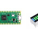
7 segment display can be controlled with a few Micropython lines from Raspberry PI Pico. It is one of simplest projects and a funny way to start coding and cabling
7 segment display is used within a wide number of applications, usually to single a display number. These devices have simple internal wiring diagrams, which maps one by one LEDs to its pins:
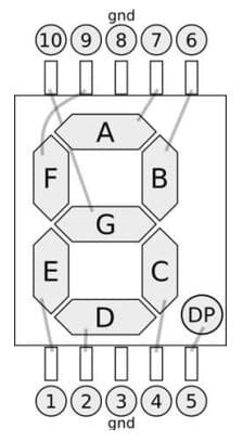
Please note that this tutorial uses a common cathode 7 segment display. This means that the common pins (3 and 8) go to the ground and each led segment is turned on when a positive value comes from RPI Pico. With common anode, the common Pind go to 3,3V and each led segment is turned on when a negative value comes from RPI Pico. In the second case, compared to my tutorial you will have to change 3 and 8 pins wiring them to Raspberry PI Pico physical pin 36 (3v3 OUT) and invert my code logic.
What We Need
As usual, I suggest adding from now to your favourite e-commerce shopping cart all the needed hardware, so that at the end you will be able to evaluate overall costs and decide if to continue with the project or remove them from the shopping cart. So, hardware will be only:
- A common computer (maybe with Windows, Linux or Mac). It can also be a Raspberry PI Computer board
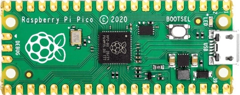
- Raspberry PI Pico microcontroller (with a common micro USB cable)
- a 7 Segment Display
- 8x resistors (220 Ohm used)
- breadboard
- dupont wirings
Step-by-Step Procedure
Wiring Diagram
Prepare cabling according to the following wiring diagram. Regarding Raspberry PI Pico pinout, you can refer my guide showing it: Raspberry PI Pico pinout
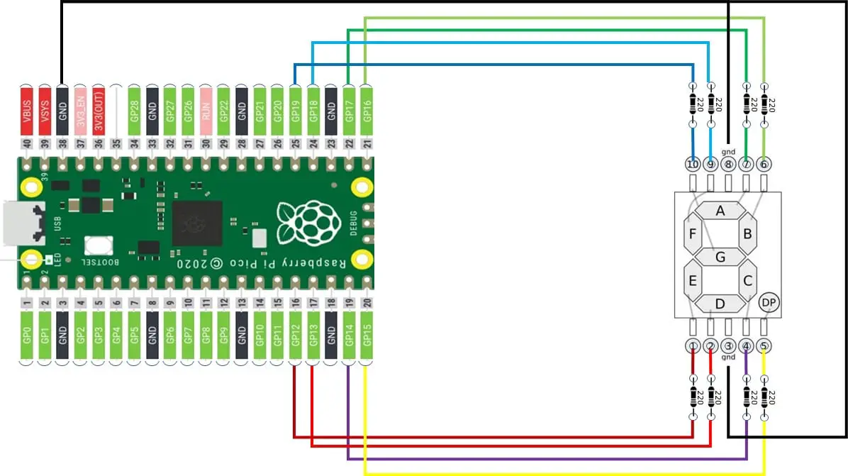
This wiring produces the following mapping between Display and Raspberry PI:
| Display Segment | Display Pin | Raspberry PI Pico GP pin |
| A | 7 | 17 |
| B | 6 | 16 |
| C | 4 | 14 |
| D | 2 | 13 |
| E | 1 | 12 |
| F | 9 | 18 |
| G | 10 | 19 |
| DP | 5 | 15 |
| GRD | 3 | GND |
| GRD | 8 | GND |
So, each Raspberry PI Pico pin powers a specific Led segment. Powering together a defined sequence of segments will display the number we want to show.
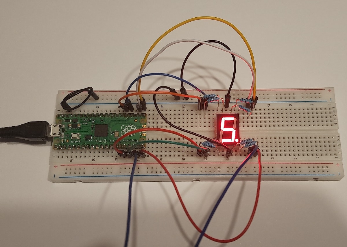
Please find below some pictures from my home lab:
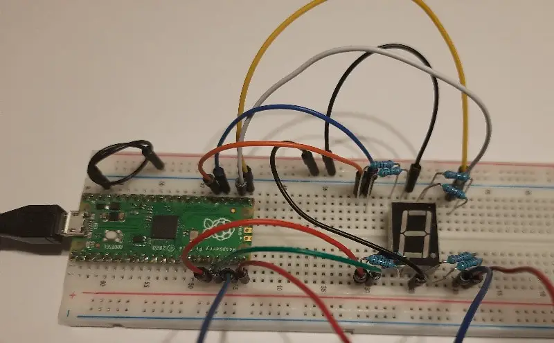
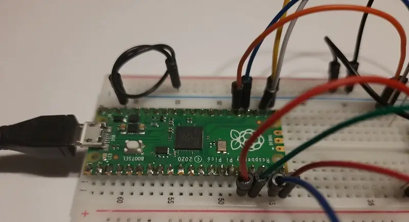
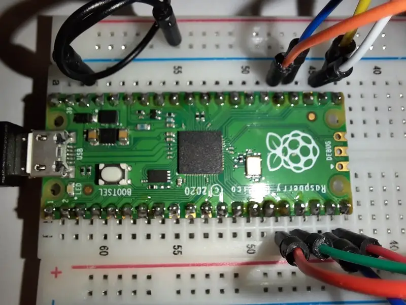
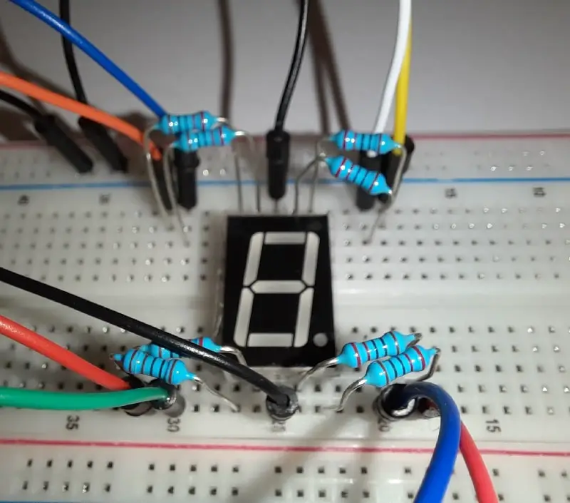
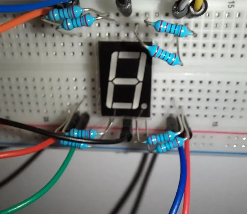
Prepare cabling according to the previous paragraph.
Get and Understand my rpiPicoSegDisplay.py Code
Connect RPI Pico to Thonny (you can refer to my tutorial about the First steps with Raspberry PI Pico).
Now download the following file to use your passive buzzer:
You can both load it in your Raspberry PI Pico storage or run it from your computer.
I’ll explain all code lines in the following paragraphs.
First of all, we import required libraries:
from machine import PinThen we define 2 variables with Pin numbers. This is a convenient way as, if you need to change wirings, you can set new GP numbers here instead of spreading around in our code. display_list collects all segments pins, ordered so that they will match A, B, C, D, E, F and G LED segments:
display_list = [17,16,14,13,12,18,19]
dotPin=15
We’ll use arrays to make our code as shorter as possible. One of these arrays will collect the PIN objects. This array is first declared and then filled with a for loop which also set pins to out mode:
display_obj = []

for seg in display_list:
    display_obj.append(Pin(seg, Pin.OUT))
Same PIN setting also for the one connected to the dot LED:
dot_obj=Pin(dotPin, Pin.OUT)Another array variable keeps a mapping of numbers with their LED configuration. For example, the number 0 (zero) has all the LED on, except the central segment (G). This will be represented by the arrSeg[0] that maps the “1,1,1,1,1,1,0” as A=1,B=1,C=1,D=1,E=1,F=1,G=0. Same logic for all other numbers:
arrSeg = [[1,1,1,1,1,1,0],\ # -> arrSeq[0] displays 0
          [0,1,1,0,0,0,0],\ # -> arrSeq[1] displays 1
          [1,1,0,1,1,0,1],\ # -> arrSeq[2] displays 2
          [1,1,1,1,0,0,1],\ # -> arrSeq[3] displays 3
          [0,1,1,0,0,1,1],\ # -> arrSeq[4] displays 4
          [1,0,1,1,0,1,1],\ # -> arrSeq[5] displays 5
          [1,0,1,1,1,1,1],\ # -> arrSeq[6] displays 6
          [1,1,1,0,0,0,0],\ # -> arrSeq[7] displays 7
          [1,1,1,1,1,1,1],\ # -> arrSeq[8] displays 8
          [1,1,1,1,0,1,1]]  # -> arrSeq[9] displays 9
Here I use a function to control the 7 segment display so that calling this function with a string representing what number we want to show (with or without the dot). This function starts converting what is received into a number (int() function) and removing the trailing dot (“.”), if present. In this way the numDisplay variable is an integer number and can be used in following for loop to configure pins output:
def SegDisplay(toDisplay):
    numDisplay = int(toDisplay.replace(".", ""))
    for a in range(7):
        display_obj[a].value(arrSeg[numDisplay][a])
Still inside the SegDisplay() function, we also manage the dot led activation by checking if the “.” is present in the input value:
    if toDisplay.count(".") == 1:
        dot_obj.value(1)
    else:
        dot_obj.value(0)
Finally, we use our function by calling it with the desired output. For example, number five with the dot led on will be call with following:
SegDisplay("5.")If we don’t want the dot, simply call in this way:
SegDisplay("5")The number can vary from 0 to 9 and the parameter needs to be a string. If you have integer numbers, you can use the str() function to convert them. An example:
SegDisplay(str(5))What’s Next
Interested to do more with your Raspberry PI Pico? Try to look at my Raspberry PI Pico tutorials for useful and funny projects!
Enjoy!

Open source and Raspberry PI lover, writes tutorials for beginners since 2019. He's an ICT expert, with a strong experience in supporting medium to big companies and public administrations to manage their ICT infrastructures. He's supporting the Italian public administration in digital transformation projects.
![]()
![]()
![]()
![]()
![]()
![]()
![]()

Hello! I want to use the str parameter but with a dot. How can i do this?
code:
x = 9(when i put the . here it exit with invalid syntax.
SegDisplay(str(x))
Thanks for help!
(i want to use the display with a stepper motor)
Hi Bertalan,
please try:
x=”.”
How would I do this with a fourteen segment display, i.e if I want to display the number 15 ?
Hi Myles,
generally, with those displays based on LED you have to create a function that converts the character you want to show into the 1 or 0 based on what leds has to be put on for that char. It can be made with a char map that makes this conversion.
After this, you will pass the 1/0 string to the display according to the display interface
Thanks for the tutorial. I’ve been trying to control multiple 7 and 16 segment displays using a 16×8 HT16K33 matrix driver backpack and the Pico but everything I’ve found online is based on the Arduino. For the life of me, I can’t even get one segment display to work with it even with Adafruit’s circuitpython drivers. Would you have any suggestions on where to start?
Hi Fred,
Please can you tell me more on your project at giuseppe@peppe8o.com? I need to know what pieces you would like to use, how you want to make them work together and what is the wished output
A really interesting project. I thought I’d give it a go but am stuck with AstronomyAPI. I have set up a user. I then try to set up the application id and there I get stuck. It asks for an origin url but I don’t have one. Any suggestions on how I can get round this.
Thanks in anticipation
Peter
Interesting API. AstronomyAPI is intended for Python (not MicroPython), so you should use a Raspberry PI computer board instead of a Raspberry PI Pico microcontroller. I will try to look at it in the next week ends. Stay tuned!
I was trying to build your moon phase project which used Astronomy API on a Pico W.
In any case my problem comes before I start coding. I want to generate an Application ID but it asks for a url but I don’t have one and don’t know how to get one.
I understand that you have other thing so I’m happy for you to take as long as you want or if it is too onerous to tell me you can’t help.
Regards
Peter
Please ignore my request as I have found the information on moon phase through a different API which doesn’t need an origin, namely Moon Phase on RapidAPI.com