
Last Updated on 13th April 2024 by peppe8o
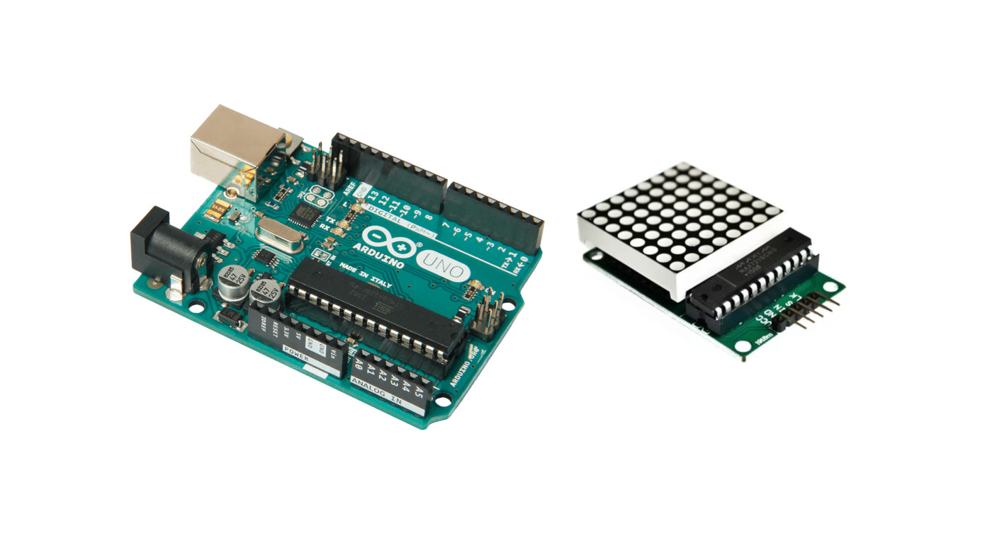
In this tutorial, we will learn how to interface MAX7219 LED Dot matrix display with Arduino. We will familiarize you with the MAX7219 dot matrix display and program Arduino to show various demonstrations of displaying texts and symbols.
To control the dot matrix with MAX7219 using Arduino and display different patterns/characters on the dot matrix.
Introduction
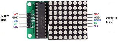
We will look into the introduction, and pinout of the MAX7219 LED dot matrix display module. It is an LED array used to display various types of texts and symbols in the form of dots which consists of LEDs. LED dot matrices are available in multiple dimensions. The MAX7219 chip makes it easier to control the dot matrix. The MAX7219 module has 5 pins. one side has the input connections and the other side has the output connections Below you can see the pinout of the Max7219 module. You can control more than one matrix at a time. For that, you just need to connect them to each other, as they have pins on both sides to extend the dot matrix.
Internal Circuit
The 8×8 matrix has 64 LEDs, 8 for each row and column. Each LED is addressed by its row and column number. Each LED refers to a dot. For making an 8×8 dot matrix all the anode terminals connect together in rows from R1 to R8, and the cathodes connect together in columns from C1 to C8. Connecting all rows and columns together is to save the required number of pins to control each LED dot. Otherwise, we will need 64 pins to control an 8×8 LED matrix. This method of controlling a large number of LEDs with few pins know as multiplexing. To reduce this complexity MAX7219 IC is available which has 24 pins. In the end, you have 5 pins to connect to the Arduino or any other microcontroller.
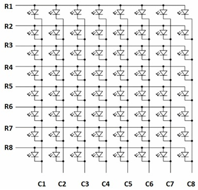
The MAX7219 chip will communicate using the SPI protocol. So you have to send requests through the 5-wire interface and through this you can control every single LED on the dot matrix.
What We Need
As usual, I suggest adding from now to your favourite e-commerce shopping cart all the needed hardware, so that at the end you will be able to evaluate overall costs and decide if to continue with the project or remove them from the shopping cart. So, hardware will be only:
Check hardware prices with the following links:


Step-by-Step Procedure
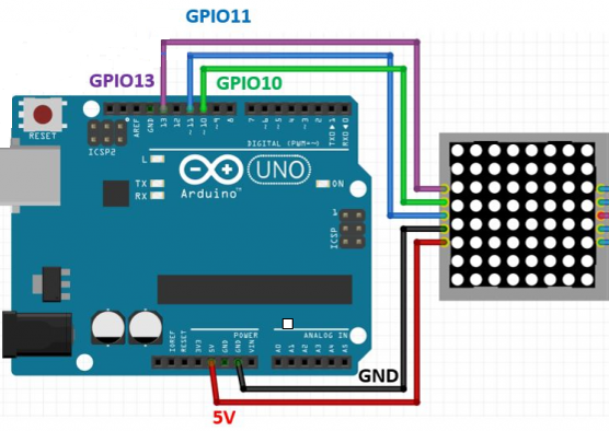
Wiring Diagram of MAX7219 with Arduino
- VCC: This pin supplies power to the MAX7219 module. It connects with the 5V pin of the Arduino.
- GND: This is the ground pin that should be associated with Arduino’s ground pin.
- DIN: This is the data_in pin. We use this as the SPI input to the module. In our case, we connect it with pin 10 of the Arduino.
- CS: This is the Chip Select pin for SPI communication. In our case, we connect it with pin 11 of the Arduino.
- CLK: This is the ‘Serial Clock’ pin for SPI serial clock output. In our case, we connect it with pin 13 of the Arduino.
When connecting a series of MAX72xx separated modules, we will use the DOUT of the first module connected to the DIN of the previous one. Please follow the wiring from the following picture, according to Arduino Uno Pinout:
Get the Max7219_code and MAX7219 library
Connect your PC to Arduino and open Arduino IDE. For the very first steps, you can refer to Connecting Windows PC with Arduino tutorial. You can get the .ino code and libraries from my download area with the following link:
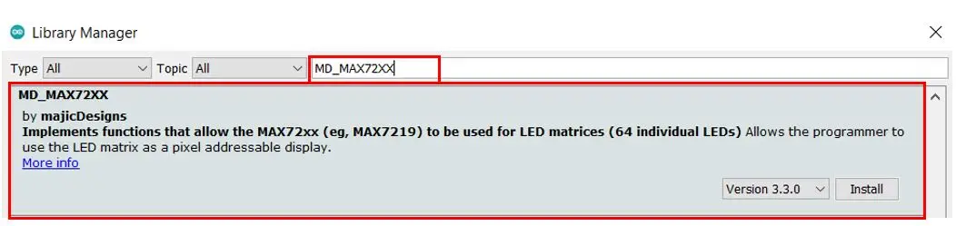
You also need to install the following library, according to my Install Arduino Libraries: methods to add libraries with Arduino IDE tutorial. Please get the .zip file from the following link or add it from the available libraries in your Arduino IDE.
Code Explanation
Section 1: Before Setup
This is the section before setup which use for globe variables defining and libraries additions. MaxMatrix.h is the library for the Max7219 dot matrix module, Through this library, we can display different characters and the animations on the dot matrix. Here we have defined the binary codes for the different characters and shapes. Like Sq will display squares, Tr is for triangles, A for displaying A and so on. Note: you can get binary codes for your custom display through this calculator.
#include <MaxMatrix.h>
int DIN = 10;   // DIN pin of MAX7219 module
int CS = 11;    // CS pin of MAX7219 module
int CLK = 13;   // CLK pin of MAX7219 module
int maxInUse = 1;
MaxMatrix m(DIN, CS, CLK, maxInUse);
char Sq[] = {8, 8,B11111111,B10000001,B10000001,B10000001,B10000001,B10000001,B10000001,B11111111};
char Tr[] = {8, 8,B00000001,B00000011,B00000101,B00001001,B00010001,B00100001,B01000001,B11111111};
char A[] = {8, 8,B00111000,B01000100,B01000100,B01000100,B01111100,B01000100,B01000100,B01000100};
char B[] = {8, 8,B01111000,B01000100,B01000100,B01111000,B01000100,B01000100,B01111000,B00000000};
char c[] = {8, 8,B00000000,B00111100,B01000000,B01000000,B01000000,B01000000,B00111100,B00000000};
char d[] = {8, 8,B00000000,B01111000,B01000100,B01000100,B01000100,B01000100,B01111000,B00000000};
char e[] = {8, 8,B00000000,B01111100,B01000000,B01000000,B01111100,B01000000,B01000000,B01111100};
char f[] = {8, 8,B00000000,B01111100,B01000000,B01000000,B01111100,B01000000,B01000000,B01000000};
Section 2: Setup Section
The serial monitor initializes at a 9600 baud rate. m.init() is for Max7219 initialization. And the m.setIntensity() is used for the intensity level of the dot matrix. For the intensity, you can use values between 0 to 15.
void setup()
{
  Serial.begin(9600);
  m.init(); // MAX7219 initialization
  m.setIntensity(5); // initial led matrix intensity, 0-15
}
Section 3: Loop
In this section, a continuous routine performs, m.clear() clear the dot matrix display. m.writeSprite(0,0,Sq) this use to display the square delay(1000) is use for one second delay. m.writeSprite(0,0,Tr) use to display the Triangle. m.writeSprite(0,0,A) use to display the A character and so on.
void loop()
{
m.clear();
m.writeSprite(0, 0, Sq);
delay(1000);
m.writeSprite(0, 0, Tr);
delay(1000);
m.writeSprite(0, 0, A);
delay(1000);
m.writeSprite(0, 0, B);
delay(1000);
m.writeSprite(0, 0, c);
delay(1000);
m.writeSprite(0, 0, d);
delay(1000);
m.writeSprite(0, 0, e);
delay(1000);
m.writeSprite(0, 0, f);
delay(1000);
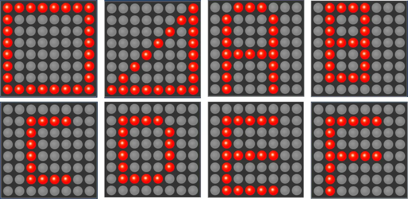
}Results
In the matrix, with each second delay, the square is displayed at first. then a triangle, After that alphabets A, B,c,d,e, and f are displayed. This displays continuously on the Matrix with a delay of one second. There is m.clear(), which is used to clear the display which comes all the sequence finished.
What’s Next
Please find more tutorials on Arduino in peppe8o Arduino archives.
Enjoy!
Umar Jamil
For any queries and help for work, please contact me at:
Whatsapp: +92-346-661-7017/ Link
Email: umarjamil0007@gmail.com

I'm an Electronic Engineer, well-skilled to solve the issues of hardware and software. I do have laboratory which contains unlimited sensors and modules for testing the working. Also, I am experienced in Arduino programming, Android mobile application, microcontroller programming, IOTs and embedded projects. I provide services to control, realize the sensor data in the Mobile Application. For any queries and help for work Contact: Whatsapp:+92-346-661-7017 Email: umarjamil0007@gmail.com
![]()


