
Last Updated on 13th April 2024 by peppe8o
In this tutorial, the Load cell connects with HX711 to interface with Arduino Uno including code, connection diagram, and component list.
To measure the weight, Load Cell with HX711 can measure up to 10g accuracy. Depending on the strength of the load, weight increases.
Introduction of Load Cell
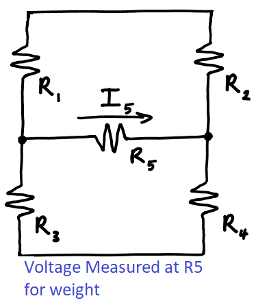
The load cell uses for the measurement of the weight. A load cell is a sensitive H-bridge circuit which has low voltage sensibility. An electronic circuit of resistors combination designed on a mechanical plate in such a way that it forms an H-bridge. Upon bending the mechanical plate the resistor values change which results in a change in measured voltage from the Load cell. This voltage is used to perform the weight measurement. The H-bridge resistors of the Load cells are very sensitive and need proper coating with glue. Glue provides mechanical protection to the load cell.
Working Principle of Load Cell
The h-Bridge circuit contains four resistors, when the load cell contains the weight, it creates mechanical stress on the plate of the load cell. This mechanical stress changes the resistance of one unique resistor (let’s say R4 ), the current R5 increases upon this stress due to this stress. Basically, R5 is the voltmeter which is measuring the voltage difference between R3 and R4. When R4 decrease then the voltage at R4 has less potential while R3 has more potential, this difference gives the voltage as a result. But we normally name it as the voltage at R5 for easiness of mind. The load cell contains four wires which are connected to the amplifier IC.
The voltage which is measured at R5 is very small and needs to be amplified so that the exact change of the voltage should be calculated. For this purpose HX711 Amplifier IC is commonly used because of its easy interface of just two wires with Arduino UNO. An explanation of the HX711 is given in the next heading.
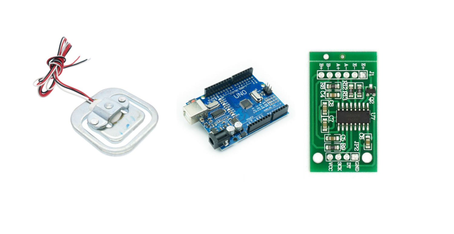
Description and Pinout of HX711 Amplifier IC
HX711 is the amplification IC, which is specifically developed for H-bridge circuits. The H-bridge circuit is balanced when all resistors are equal. The circuit board of this IC contains 6 inputs, two power VCC and GND and 2 for control pins. It works on 5V and takes up to 22uA in sleep mode, while in the working mode it takes up to 60 mA.
| Sr. | Pin Name | Working on the PIN |
| 1 | VCC | The voltage pin needs to be connected with 5V. |
| 2 | SCK | Clock pin connected to any GPIO |
| 3 | DT | Data pin connected to any GPIO (e.g:4,5,6) |
| 4 | GND | Ground pin connected to GND (Zero Volt) |

Load cell wires are connected to the left side of the Amplifier IC (HX711) to pins E+ till A+. This is explained in the load cell section.
Load Cell Description and pinout
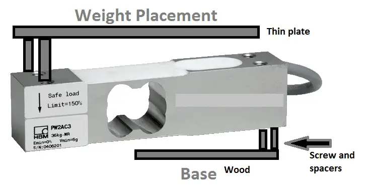
A load cell is a transducer, the transducer is an electrical device that transforms energy from one form to another. Thermometers, microphones, loudspeakers, position and pressure sensors, and antennas are all examples of devices that generate an electrical signal that is proportional to the force being measured. Pneumatic load cells, hydraulic load cells, and strain gauge load cells are some of the several types of load cells. The weight acts on the load cell’s metal spring component during measurement, causing elastic deformation. A strain gauge (SG) fitted on the spring element converts the strain (positive or negative) into an electrical signal. A bending beam with a strain gauge is the most popular type of load cell. Straight one load cell is not assembled while the rectangular shape does not require any assembly. So it’s better to choose a rectangular one to avoid mechanical work.
What We Need
As usual, I suggest adding from now to your favourite e-commerce shopping cart all the needed hardware, so that at the end you will be able to evaluate overall costs and decide if to continue with the project or remove them from the shopping cart. So, hardware will be only:
Check hardware prices with the following links:


Step-by-Step Procedure
Connection with Arduino
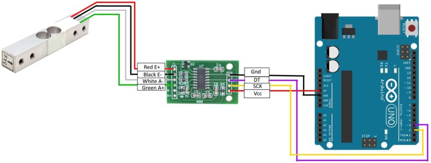
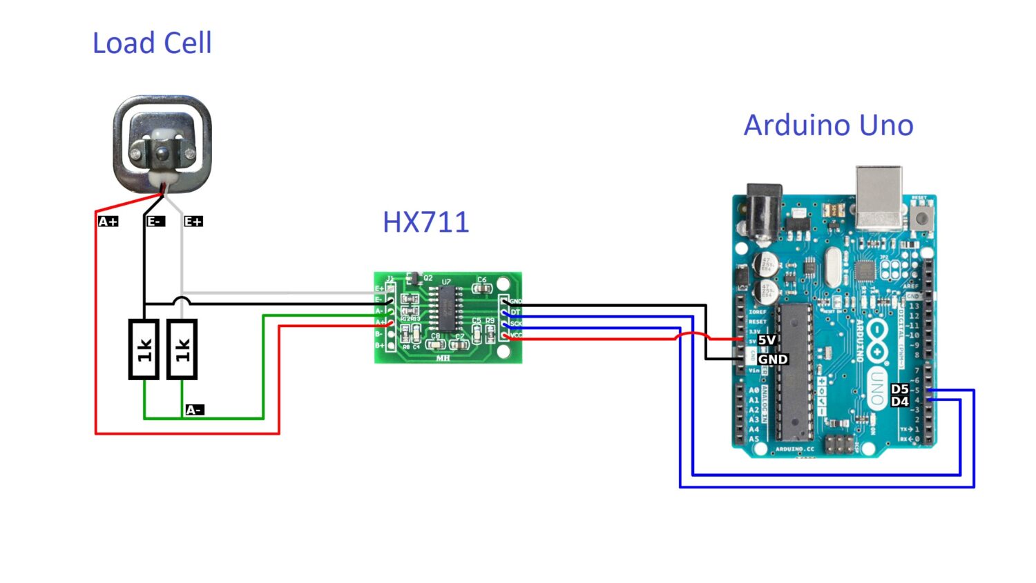
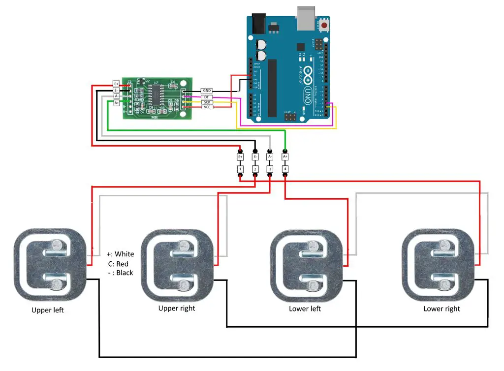
As shown in the image below, the sensor connects with Arduino Uno. Please follow the wiring that, according to Arduino Uno Pinout to make the connections.
In the connection will be providing 3 diagrams depending on the wires of the load cells as they come in 3 and 4 wires.
With 4 wires load cell, four combinations will be like this, each red will be connected with the red wire, black with black, white with white and green with green.
Get Weight_loadcell.ino and Code Explanation
Connect your PC to Arduino and open Arduino IDE. For the very first steps, you can refer to Connecting Windows PC with Arduino tutorial. You can get the .ino code from my download area with the following link:
You also need to install the following library, according to my Install Arduino Libraries: methods to add libraries with Arduino IDE tutorial:
The .ino code is distributed in three major parts, part 1 before setup, part 2 setup and part 3 loop. Starting with section 1:
Section 1: Libraries of HX711, pins defining and global variables perform. In the current scenario, callibration_factor (CF) is important to understand. This is the amplification factor used for converting the voltage of the load cell into weight. CF has its importance because the accuracy of the resulting weight is depending on it. Each load cell of 20kg, 50 kg, and 100 kg has its own calibration factor. Depending on the multiplication ratio. For experimentation results, For 50kg CF = 62. For 20 kg, 113.
#include "HX711.h"
HX711 scale;
float callibration_factor = 2280.f;
Section 2: Setup
The serial monitor opens at a baud rate of 38400. HX711 IC initialise and calibrated at CF. Reading of the weight taken before and after the calibration so that we can compare readings for better results.
void setup() {
  Serial.begin(38400);
  Serial.println("HX711 Demo");
  Serial.println("Initializing the scale");
  scale.begin(A1, A0);

  reading_value();
  scale.set_scale(callibration_factor); // callibration factor can be called as the multiplication factor of amplification of the voltage
  scale.tare();                // reset the scale to 0

  Serial.println("After setting up the scale:");
  Serial.print("read: \t\t");
  reading_value();
}
Section 3: Loop Section
In the loop section, we continuously measure the value of weight. There are 3 commands which are used at multiple times.
The scale.getunit(): this command gets the reading one time. If written as scale.getunit(10), measurement is made 10 times and its average is presented.
Similarly, scale.read_average(20) prints the value without subtracting the tares. Tares is the initial value soon after the calibration, this value is the vibration value which varies between 10 and 50.
void loop() {
  Serial.print("one reading:\t");
  Serial.print(scale.get_units(), 1);
  Serial.print("\t| average:\t");
  Serial.println(scale.get_units(10), 1);

  scale.power_down();             // put the ADC in sleep mode
  delay(5000);
  scale.power_up();
}

void reading_value()
{
  Serial.println(scale.read());      // print a raw reading from the ADC
  Serial.print("read average: \t\t");
  Serial.println(scale.read_average(20));   // print the average of 20 readings from the ADC
  Serial.print("get units: \t\t");
  Serial.println(scale.get_units(5), 1);  // print the average of 5 readings from the ADC minus tare weight (not set) divided
}
What’s Next
Please find more tutorials on Arduino in peppe8o Arduino archives.
Enjoy!
Umar Jamil
For any queries and help for work, please contact me at:
Whatsapp: +92-346-661-7017
Email: umarjamil0007@gmail.com

I'm an Electronic Engineer, well-skilled to solve the issues of hardware and software. I do have laboratory which contains unlimited sensors and modules for testing the working. Also, I am experienced in Arduino programming, Android mobile application, microcontroller programming, IOTs and embedded projects. I provide services to control, realize the sensor data in the Mobile Application. For any queries and help for work Contact: Whatsapp:+92-346-661-7017 Email: umarjamil0007@gmail.com
![]()


