
Last Updated on 1st November 2023 by peppe8o
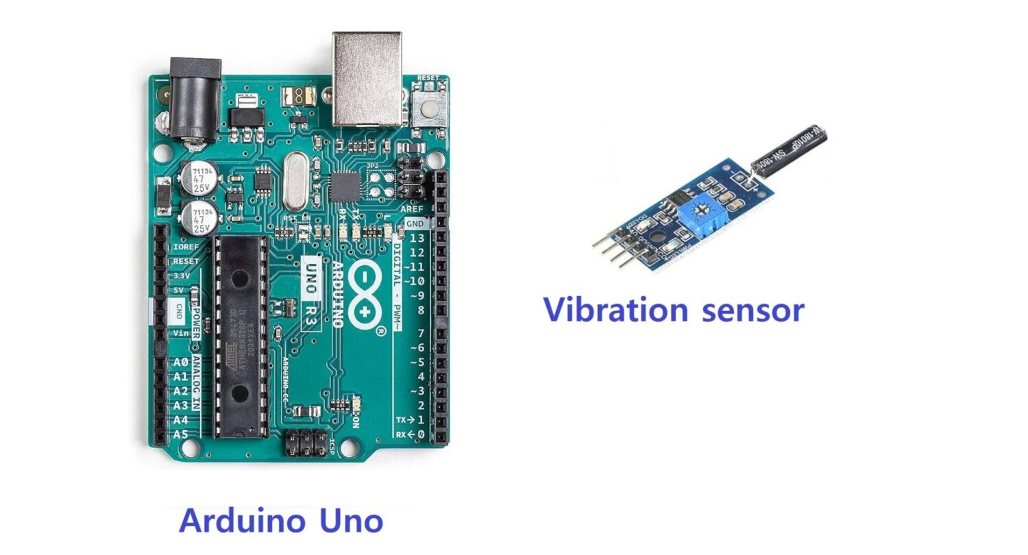
In this tutorial, we will use a vibration sensor module with Arduino Uno to control the on / off state of a system, based on vibration feedback.
It is most used in preventing theft and security systems such as money lockers to avoid much damage.
Vibration sensor SW-18015P Description
The vibration switch is a digital component or subsystem that various devices use to keep track of vibration. It has high sensitivity and can detect small vibrations.
It has applications in alarms, electronic lockers and other security devices. The output of the vibration sensor is low when it detects the vibration, or high when it doesn’t (inverted logic). This means that it works on TTL logic (0 or 5V) for the microcontroller.
They usually adopt a SW-18010P vibration sensor, as shown in the following picture:
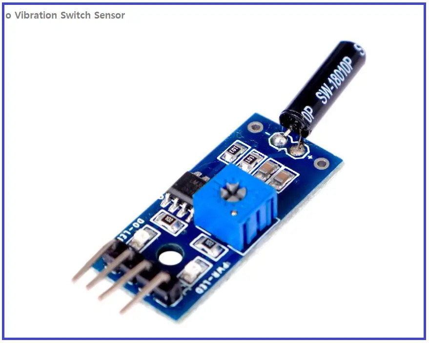
Working Principle of the SW-18010P
The circuitry of the vibration sensor consists of a conductive plate which gets energised at small vibrations. There is a spring and a contact plate: when the sensor feels a vibration it makes the contact plate touch the electrode on which the circuit is closed.
SW-18015P Pinout
Usually, there are three pins in the sensor module:
- The VCC works on 3.3 or 5 V depending on the circuit inside.
- The DO is the digital output which connects with the microcontroller. As the module works on a
- The GND connects with the ground of the controller.
The SW-18015P vibration switch modules also include an A0 PIN, providing an analog output with a voltage signal proportional to the vibration intensity.
What We Need

As usual, I suggest adding from now to your favourite e-commerce shopping cart all the needed hardware, so that in the end you will be able to evaluate overall costs and decide if continue with the project or remove them from the shopping cart. So, hardware will be only:
Step-by-Step Procedure
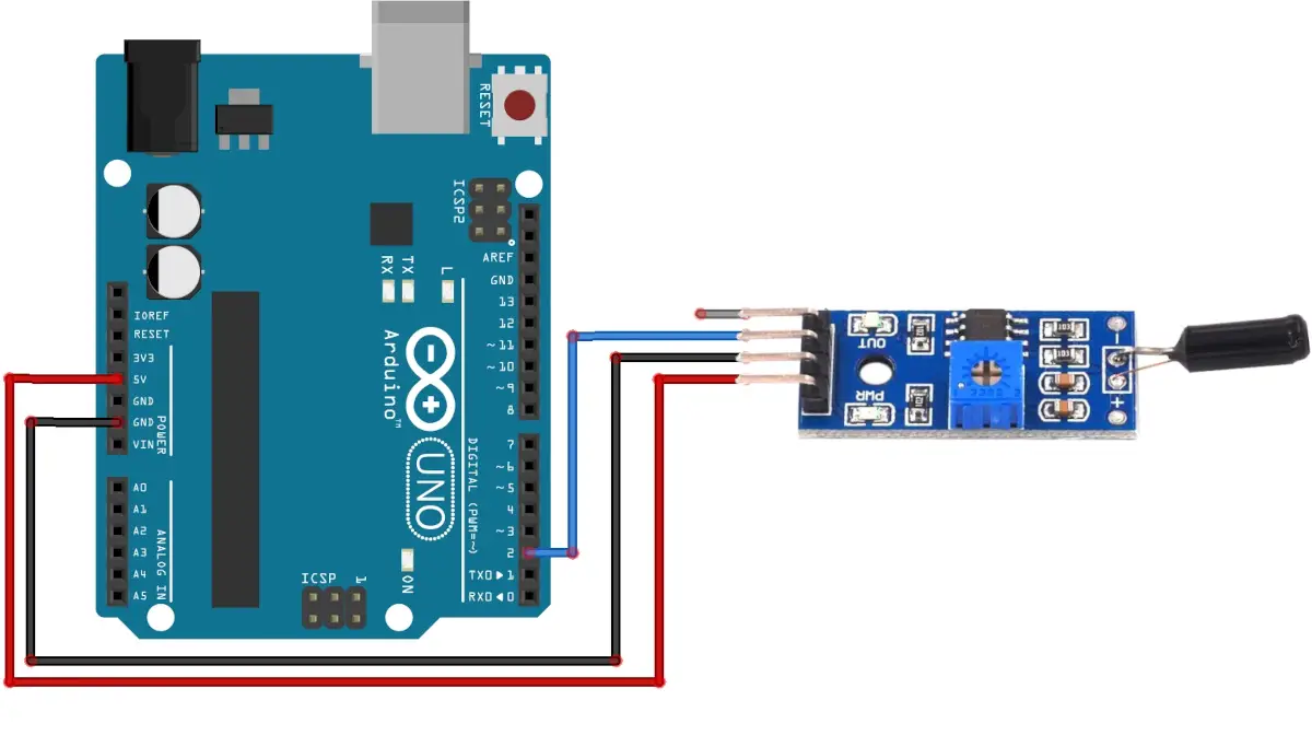
Wiring Diagram of vibration switch with Arduino Uno
The vibration sensor requires three pins to connect to the microcontroller. There are GND, Data and VCC on the vibration sensor which requires connecting. The GND and VCC pins on the sensor connected to the GND and 5V of Arduino Uno respectively. The data pin connects with pin 2 of Arduino Uno.
| Vibration sensor | Arduino |
|---|---|
| AO (PIN 1) | Not connected |
| DO (Pin 2) | Pin 2 |
| GND (Pin 3) | GND |
| VCC (Pin 4) | 5 V |
Please find below a picture showing the vibration sensor and Arduino Uno wiring diagram:
Get the code for the vibration sensor with Arduino
Connect your PC to Arduino and open Arduino IDE. For the very first steps, you can refer to Connecting Windows PC with Arduino tutorial. You can get the .ino code from my download area with the following link:
Code Explanation
Section 1: Before setup
In this section, we attach the vibration sensor at PIN 2 of Arduino Uno. In order to make the code clean, we associate the PIN number with a variable.
We also initialize the vibrationdetected boolean variable to false. It will drive the serial monitor printing: when vibration is detected it is set to true, while when no vibration is detected it is set to false.
The count variable deals with the number of detections.
int vibrationSensorPin = 2;
bool vibrationDetected = false;
int count =0;
Section 2: In the setup
In the setup, we set the baud rate of the serial monitor to 9600. Then, we initialize the sensorpin as INPUT_PULLUP because it sensor sends LOW logic when vibration is detected.
void setup() {
  Serial.begin(9600);
   pinMode(vibrationSensorPin, INPUT_PULLUP);
}
Section 3: Loop section
This is the section for the main loop.
In this, the value of the sensor is read by the digitalRead command. When it is LOW, a vibration feedback has been detected.
void loop() {
  if (digitalRead(vibrationSensorPin) == LOW) {
At this stage, we increment the count variable, which is printed on the serial monitor for vibration detection, together with a “Vibration detected” notice.
The code also sets the vibrationdetected variable to true so that the print statement will not be displayed continuously. Then the code waits for 1 second before repeating the loop.
    count++;
    Serial.print("Count =");
    Serial.print(count);
    Serial.println("Vibration detected, HIGH logic from SENSOR");
    vibrationDetected = true;
    delay(1000);
If no vibration is detected then the serial monitor prints “NO vibration detected”, and sets the vibrationdetected variable to false so that in case of no vibration then it should not print continuously.
} else {
if (vibrationDetected) {
Serial.println("No vibration detected, LOW logic from SENSOR");
vibrationDetected = false;
}
}
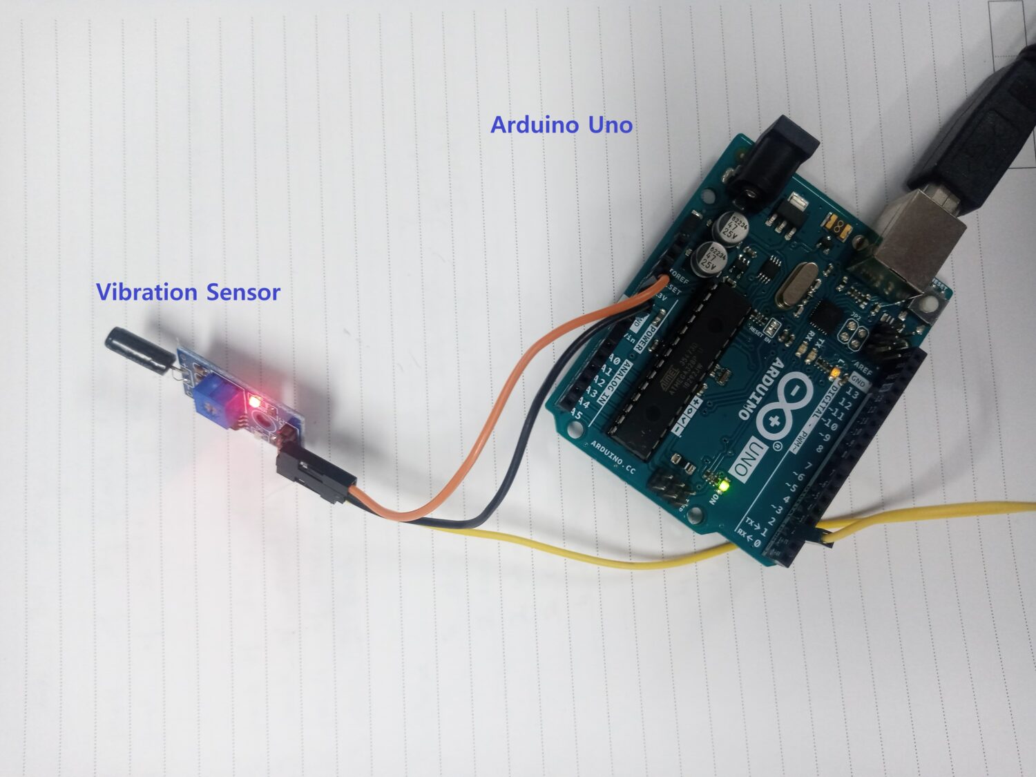
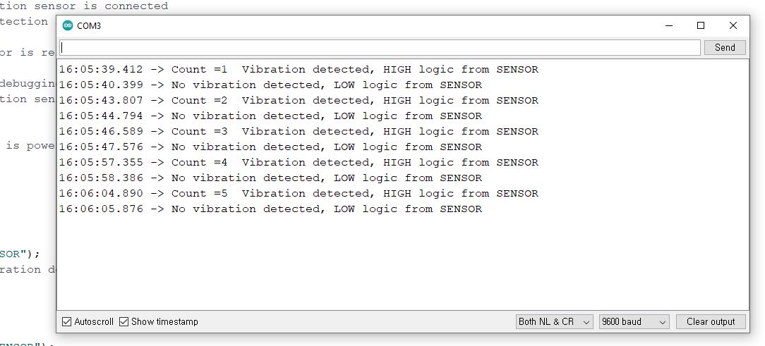
}Results
Here are the results for the vibration sensor interface with Arduino Uno.
When we touch the sensor, the circuit detects it. The serial monitor shows the vibration sensor detected and its count increase. The test is performed after some duration for validity.
When the sensor is in the resting stage, it prints NO vibration detected.
What’s Next
Please find more tutorials on Arduino in peppe8o Arduino archives.
Enjoy!
Umar Jamil
For any queries and help with work, please contact me at:
Whatsapp: +92-346-661-7017/ Link Fiverr for order custom work
Email: umarjamil0007@gmail.com

I'm an Electronic Engineer, well-skilled to solve the issues of hardware and software. I do have laboratory which contains unlimited sensors and modules for testing the working. Also, I am experienced in Arduino programming, Android mobile application, microcontroller programming, IOTs and embedded projects. I provide services to control, realize the sensor data in the Mobile Application. For any queries and help for work Contact: Whatsapp:+92-346-661-7017 Email: umarjamil0007@gmail.com
![]()


