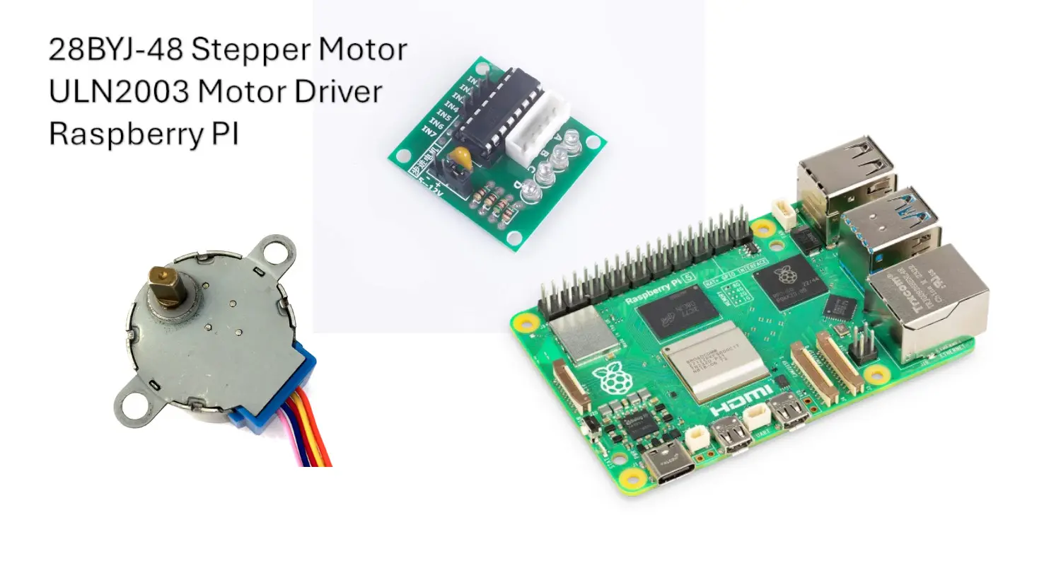
In this tutorial, I will show you how to interface and use a 28BYJ-48 stepper motor with Raspberry PI computer boards, including the Python code (explained). Please note that if you need to use this motor with Raspberry PI Pico microcontroller, you can refer to my Stepper Motor with Raspberry PI Pico: 28BYJ-48 and ULN2003 wiring and MicroPython code tutorial.
In my projects with Raspberry PI, I have always been fascinated by the infinite fields of application for this fantastic board. One of my preferred fields is robotics, which requires the control of arms, wheels, and gears using motors.
Because of their precision, Stepper motors are the most common motor type in commerce for these projects.
About the 28BYJ-48
As defined by Wikipedia: “A stepper motor, also known as step motor or stepping motor, is a Brushless DC electric motor that rotates in a series of small and discrete angular steps. Stepper motors can be set to any given step position without needing a position sensor for feedback. The step position can be rapidly increased or decreased to create continuous rotation, or the motor can be ordered to actively hold its position at one given step. Motors vary in size, speed, step resolution, and torque.”
The following picture, from the same Wikipedia page, shows the main working principle of a stepping motor:
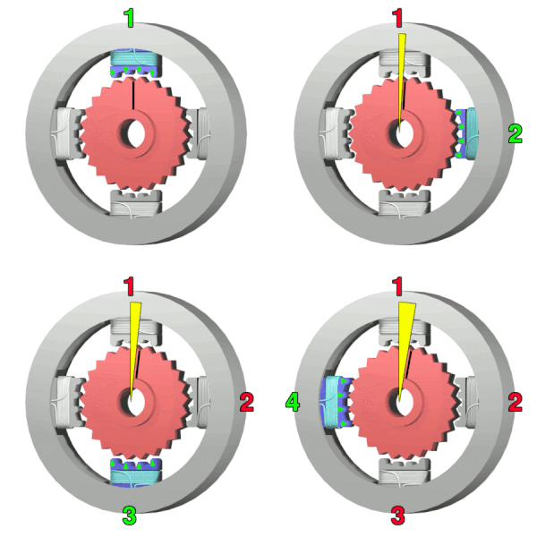
The teeth of the gear-shaped iron rotor are always attracted by the nearest magnet. In the picture, there are 4 magnets, each one allocated to a different phase of these teeth. In this way, activating one magnet at time, will attract the teeth and move the rotor to a different position. By activating the magnets in a specific order, the rotor will rotate in the desired direction.
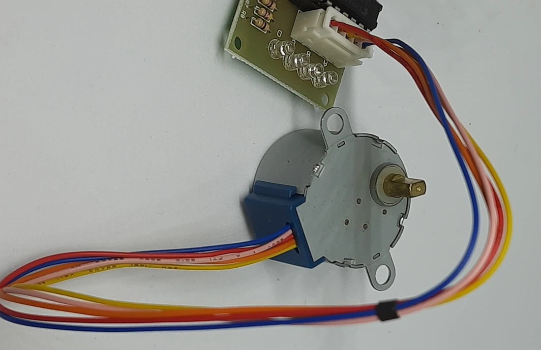
The 28BYJ-48 uses transistors to produce the magnetic force. Even if they could be used directly from our Raspberry PI, a motor driver like the ULN2003 will make the interfacing and driving operations far simpler for a beginner. This is the reason why the 28BYJ-48 stepper motor and the ULN2003 motor driver are one of the most popular for hobbyists.
Driving the 28BYJ-48 with ULN2003
The ULN2003 has 4 main inputs, besides the power inputs: IN1, IN2, IN3, and IN4. When using it, we can perform a stepper rotation by using the following sequences to the motor driver inputs:
| SEQ0 | SEQ1 | SEQ2 | SEQ3 | SEQ4 | SEQ5 | SEQ6 | SEQ7 | |
| IN4 | 1 | 1 | 0 | 0 | 0 | 0 | 0 | 1 |
| IN3 | 0 | 1 | 1 | 1 | 0 | 0 | 0 | 0 |
| IN2 | 0 | 0 | 0 | 1 | 1 | 1 | 0 | 0 |
| IN1 | 0 | 0 | 0 | 0 | 0 | 1 | 1 | 1 |
By repeating this sequence you will get the stepper motor rotating in a specific direction. By performing the sequence in the inverse direction, you will get the stepper motor rotating in the inverse direction.
What We Need
As usual, I suggest adding from now to your favourite e-commerce shopping cart all the needed hardware, so that at the end you will be able to evaluate overall costs and decide if to continue with the project or remove them from the shopping cart. So, hardware will be only:
- Raspberry PI Computer Board (including proper power supply or using a smartphone micro USB charger with at least 3A)
- high speed micro SD card (at least 16 GB, at least class 10)
- Dupont wirings (in my configuration, I will use 6x female-female)
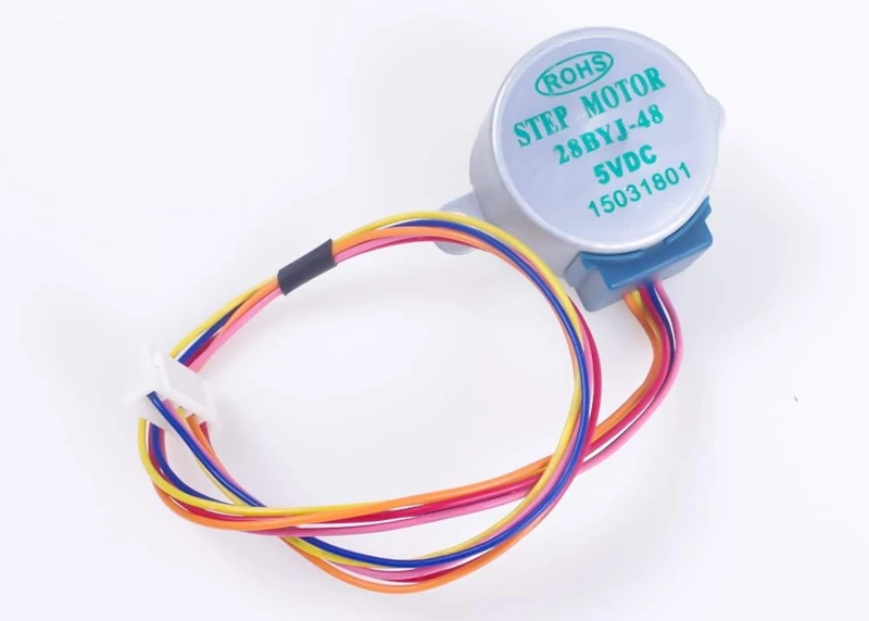
- 28BYJ-48 stepper motor with the ULN2003 motor driver
IMPORTANT: Before Starting (additional HW)
Before starting, let me expose some considerations on hardware.
As with many motors, the stepper motors drain a lot of current. While the Raspberry PI computer boards have a 5V out PIN, draining a lot of current for a long time from these PINs could break your Raspberry PI. Certainly, you can use the 5V PINs from Raspberry PI with a stepper motor for short tests to check if your program works, but I strongly suggest to use to an external power supply for the stepper motor (via the motor driver).
Wiring Schema for Stepper Motor and Raspberry PI with Motor Driver
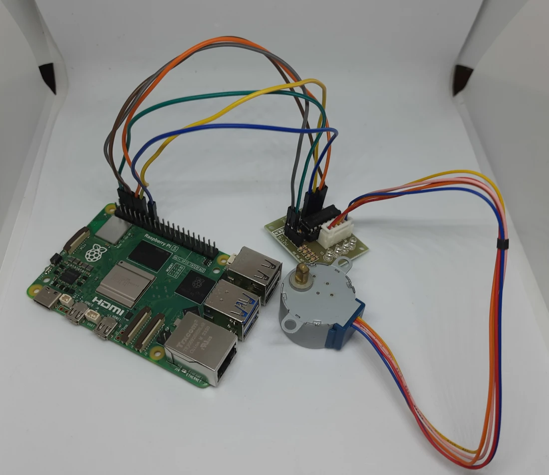
The following picture shows how connections have been cabled in my lab, according to the Raspberry PI Zero Pinout:
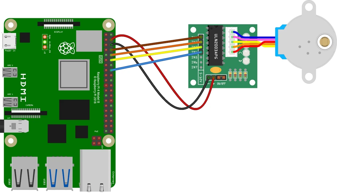
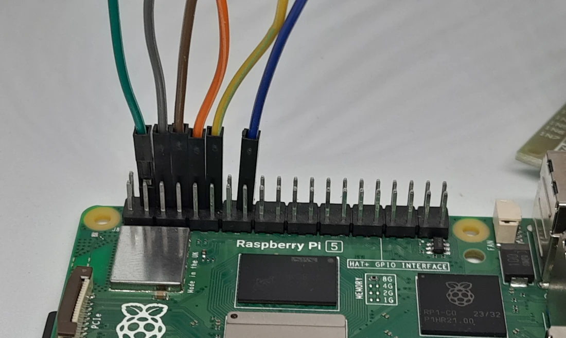
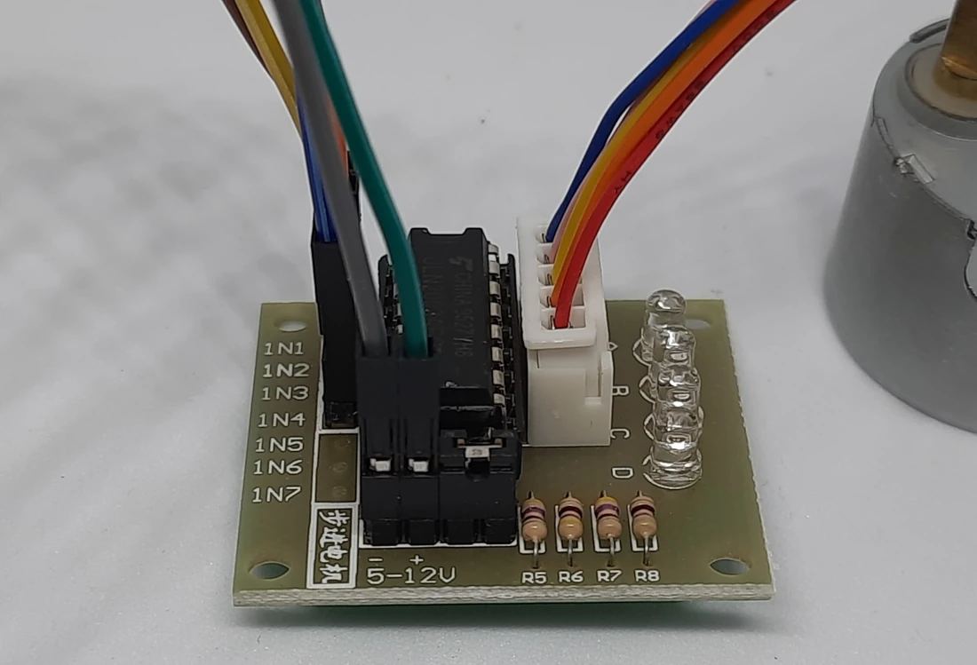
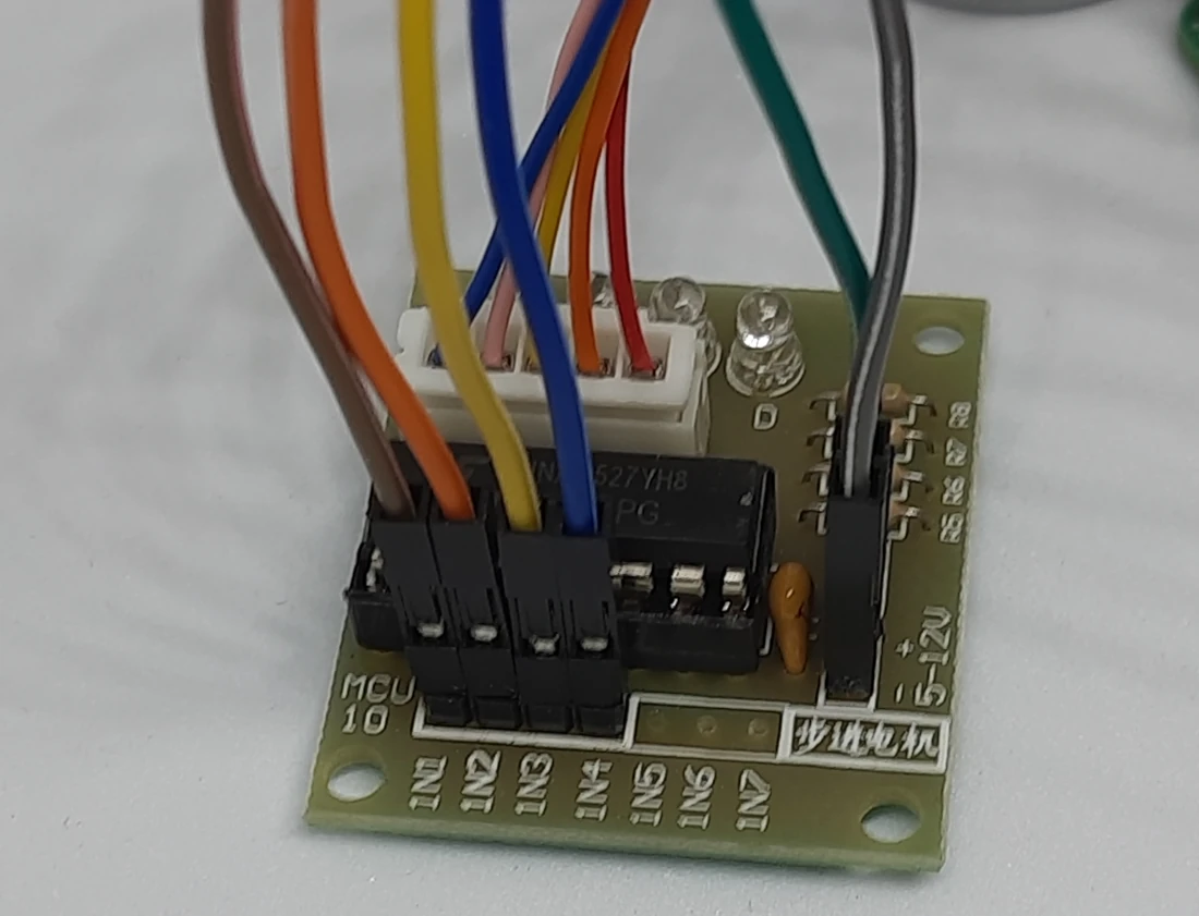
The stepper motor comes with a pre-installed connector that you can directly connect to the ULN2003 controller. All other connections are made with Dupont cables. Please find below a connection table, that will help you in arranging the cables:
| Raspberry PI | ULN2003 motor driver | 28BYJ-48 stepper motor |
|---|---|---|
| 5V | + (12V) | |
| GND | – (5V) | |
| 14 | IN1 | |
| 15 | IN2 | |
| 18 | IN3 | |
| 23 | IN4 | |
| A/B/C/D (one cable) | Stepper motor cable |
IMPORTANT: with a 5V power supply for the ULN2003, it is important to set properly the power bridge as shown in the following pictures, so that we make it work with a 5V logic.
Moreover, some pictures from my home lab follow:
Prepare the Operating System
The first step is installing the Raspberry PI OS Lite (please note that we need the 64-bit version) to get a fast and light operating system (headless). In this case, you will need to work from a remote SSH terminal.
If you need a desktop environment, you can also use the Raspberry PI OS Desktop, in this case working from its terminal app.
Please find the differences between the 2 OS versions in my Raspberry PI OS Lite vs Desktop article.
Make sure that your OS is up to date. From your terminal, use the following command:
sudo apt update -y && sudo apt upgrade -yUse Stepper Motor and Raspberry PI in Python Projects
Now we need a Python script to control the stepper motor with our Raspberry Pi. For this purpose, I prepared a simple Python script. You can just download it and align the script to your wiring configuration (if you changed the GPIO connections):
wget https://peppe8o.com/download/python/steppermotor/stepper.pyIf you need to align code to your customized wiring or if you need to change the stepper motor delay, edit it with the following terminal command:
nano stepper.pyThe following will explain the script line by line.
At the beginning, we’ll import the required libraries. It is important to note that we’ll use the gpiozero library (already included in all the newest Raspberry PI OS versions), so we don’t need to install any specific package:
import sys
from time import sleep
from gpiozero import DigitalOutputDevice
The following 3 variables will help to keep the code clean.
The motor_GP will include the PINs of our Raspberry PI, ordered according to what are connected to the IN1, IN2, IN3, and IN4 input of ULN2003.
We’ll use the seq_pointer variable to call the sequence step to perform, as numbered in the capter describing the working principle of 28BYJ-48 with ULN2003.
The stepper_obj variable is an empty list which we’ll fill with the Raspberry PI’s PIN objects:
motor_GP = [14,15,18,23]
seq_pointer=[0,1,2,3,4,5,6,7]
stepper_obj = []
Another important variable is the arrSeq, which lists the inputs to drive by the ULN2003 as already discussed:
arrSeq = [[0,0,0,1],\
          [0,0,1,1],\
          [0,0,1,0],\
          [0,1,1,0],\
          [0,1,0,0],\
          [1,1,0,0],\
          [1,0,0,0],\
          [1,0,0,1]]
Before going to the program’s tasks, the code will fill the stepper_obj list by initializing all the GPIO PINs and setting them as output. This will be made with a for loop. This task is notified to the console with the “print” statement:
print("Setup pins...")
for gpio in motor_GP: stepper_obj.append(DigitalOutputDevice(gpio))
The stepper_move() custom function enables you to control the 28BYJ-48 stepper motor from a single line, as we’ll see in the main program. It requires 2 inputs:
- direction: possible values are -1, 0, and 1. -1 and 1 will move the rotor clockwise / anticlockwise, while 0 will stop the rotation
- speed: possible values are from 1 to 5. It sets the rotation speed
This function gets the seq_pointer variable from the main context (this is why we call it with the “global” statement).
def stepper_move(direction, speed): # direction must be +1 or 0 or -1, speed must be between 1 and 5
    global seq_pointer
Then it performs a rotation of the seq_pointer list, so that the “seq_pointer[0]” will always include the values to be set at the ULN2003 input PINs for the next step. These values are set at the Raspberry PI PINS in the following “for” loop:
    seq_pointer=seq_pointer[direction:]+seq_pointer[:direction]
    for a in range(4): stepper_obj[a].value = arrSeq[seq_pointer[0]][a]
The final line of the custom function adds a very small sleep time between every step. It is really important as it manages the input timing from the Raspberry PI. In my tests (with a Raspberry PI 5 model B), having a lower or higher sleep time outside the 1 and 5 milliseconds range gave me problems with the stepper motor (it was simply not rotating). Adding this sleep time was making my stepper motor to correctly work. If the 28BYJ-48 doesn’t work for you with your Raspberry PI model, you can try reducing or incrementing this value.
Moreover, dividing 0.005 by the “speed” variable (having values between 1 and 5) will mean that the resulting sleep time will always be between 0.001 and 0.005.
sleep(0.005/speed)With that, the main script block will be just a call to my stepper_move() custom function inside a “while” loop:
while True:
    stepper_move(1, 5)
You can now save and close the file (CTRL+X).
Run The Stepper Motor from Raspberry PI
Now you can easily test your stepper motor with Raspberry PI by issuing the following command:
python3 stepper.pyand you should see the motor rotating. You can stop the program at any time by pressing CTRL+C in your terminal console.
Next Step
Interested in more RPI projects? Take a look at peppe8o Raspberry PI tutorials.
Enjoy!
Open source and Raspberry PI lover, writes tutorials for beginners since 2019. He's an ICT expert, with a strong experience in supporting medium to big companies and public administrations to manage their ICT infrastructures. He's supporting the Italian public administration in digital transformation projects.

