Last Updated on 2nd June 2024 by peppe8o
In this tutorial I’m going to show you how to connect and put into work an analog joystick with Raspberry PI Pico, using MicroPython.
Joysticks are common input devices widely used in games, but in some cases they can also replace mouse when we need to attach them in a small space. Joysticks can work with Raspberry PI Pico as this microcontroller has analog inputs
The Joystick Module
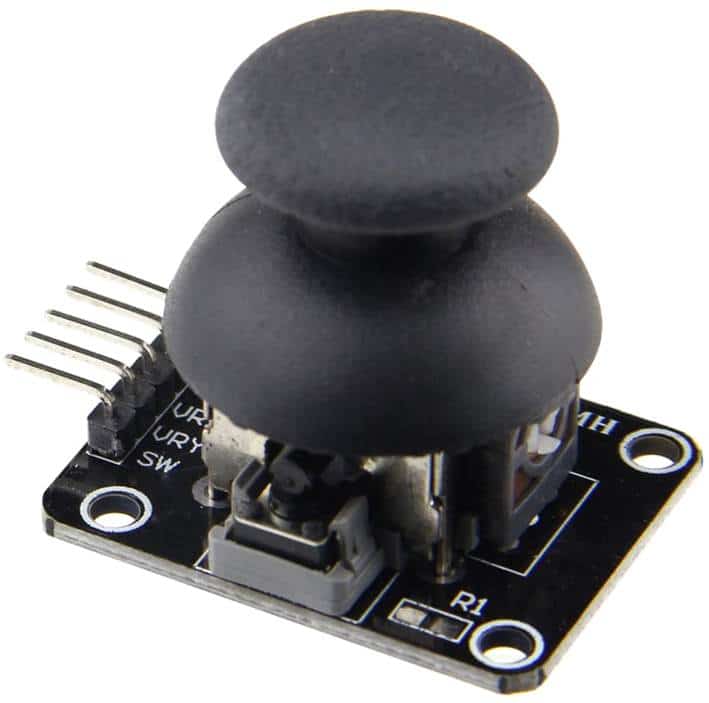
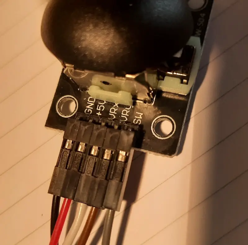
Joysticks are user devices allowing to input 2 analog parameters by using fingers. Common joystick modules available from e-commerce markets also include a switch function when pressing the knob.
They have 5 connectors: 5V for Vcc, Ground, x-axis reference output, y-axis reference output, and the switch output. As this device works at 5V Vcc, you should put attention to limit references in order to avoid circuits breaking in microcontrollers (like Raspberry PI Pico) which “prefers” 3,3 V inputs. On the other side, Raspberry PI Pico can read from its analog inputs only ranges between 0 and 3,3V. For this reason we’ll need a voltage reduction circuit with resistors (similarly to the one needed to control a ultrasonic distance sensor with Raspberry PI).
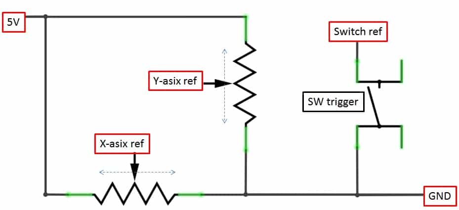
The analog joystick internal circuit is composed of 2 potentiometers (connected to X and Y axis) where vertical and horizontal positions are collected. When also a switch function is available, a common mini switch button is included in the module:
What We Need
As usual, I suggest adding from now to your favourite e-commerce shopping cart all the needed hardware, so that at the end you will be able to evaluate overall costs and decide if to continue with the project or remove them from the shopping cart. So, hardware will be only:
- A common computer (maybe with Windows, Linux or Mac). It can also be a Raspberry PI Computer board
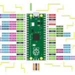
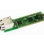
- Raspberry PI Pico microcontroller (with a common micro USB cable)
- resistors (I used 6x 220 Ohm)
- analog joystick module
- breadboard
- dupont wirings
Check hardware prices with following links:


Wiring Diagram
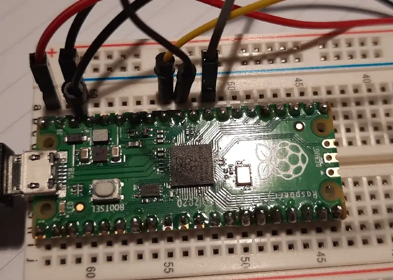
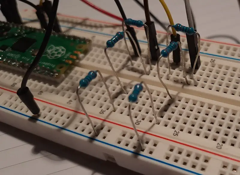
Please find below a picture showing my wiring diagram:
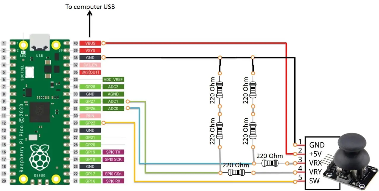
As you can see, I’m using 2 resistors, with the same value, in series for my voltage reduction circuit. In this way I’m avoiding to find a 440 ohm resistor.
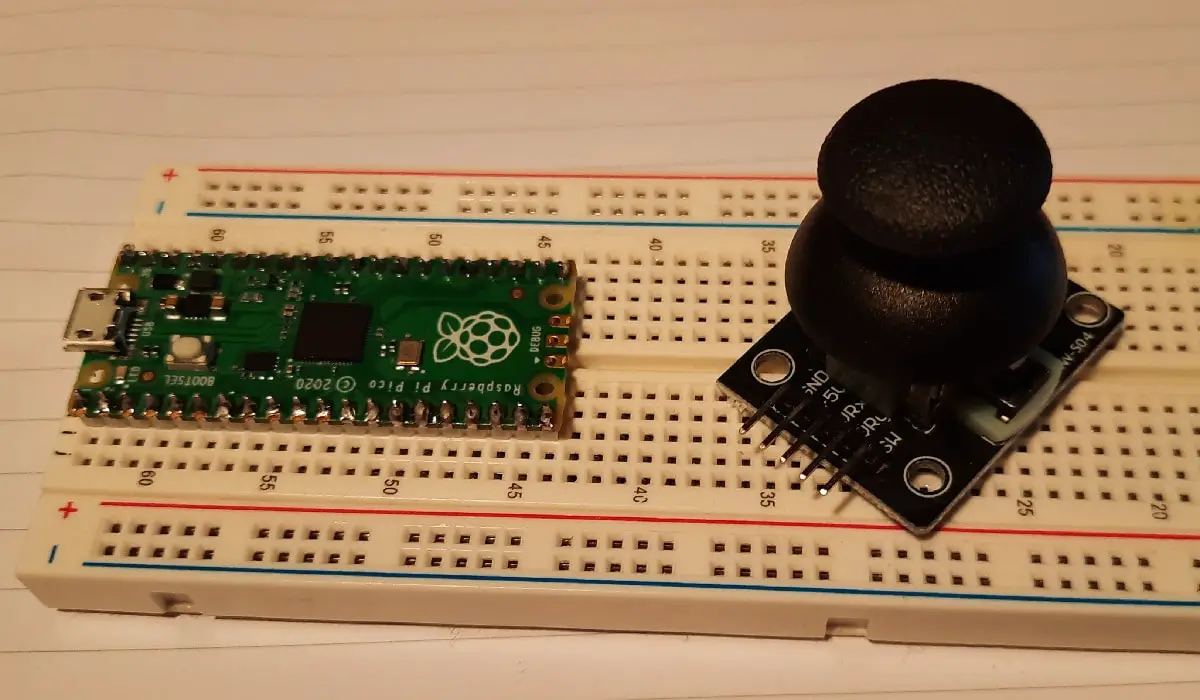
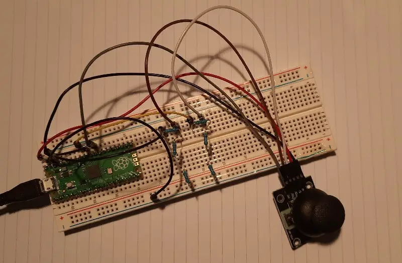
Please find below some detail pictures from my lab:
Step-by-Step Procedure
Connect RPI Pico to Thonny (you can refer to my tutorial about First steps with Raspberry PI Pico). Download my picoJoystick.py script on your computer and open it with Thonny.
Following paragraphs will describe my code line by line. At the end, you will find scipt expected results.
Start importing required modules:
from machine import ADC, Pin
import utime
Use variables to map cabling in your code. This allows changing wiring according to your needs without re-writing each occurrence in your code, also improving code readability. Xaxis, yAxis, and SW pins are numbered according to Raspberry PI Pico pinout. readDelay will add time between each reading so that you can see results when moving your analog Joystick. SW is also software-configured with a pull-up resistor so that when the switch button is open it goes to 1 (please refer to my Switch Button with Raspberry PI tutorial for more info):
xAxis = ADC(Pin(26))
yAxis = ADC(Pin(27))
SW = Pin(22,Pin.IN, Pin.PULL_UP)
readDelay = 0.5
Here the main loop comes. Analogue values reading uses the “read_u16” function (which reads unsigned 16-bit values):
while True:
    xRef = xAxis.read_u16()
    yRef = yAxis.read_u16()
Also switch button state is read as a simple digital input:
SWPushed= SW.value()And results are printed to Thonny shell:
print("X: " + str(xRef) +", Y: " + str(yRef) + ", SW: " + str(SWPushed))Our script then waits for a “readDelay” time before restarting the main loop:
utime.sleep(readDelay)Run picoJoystick.py Script
In our Thonny IDE, run this code (F5). You can both save it to your local computer or in your Raspberry PI Pico (if asked). Your shell will start printing analog joystick position and switch state as following:
MicroPython v1.15 on 2021-04-18; Raspberry Pi Pico with RP2040

Type "help()" for more information.
>>> %Run -c $EDITOR_CONTENT
X: 7937, Y: 8418, SW: 1
X: 7937, Y: 8418, SW: 1
X: 7841, Y: 8402, SW: 1
X: 7921, Y: 8402, SW: 1
X: 7905, Y: 8402, SW: 1
X: 7921, Y: 8402, SW: 1
X: 320, Y: 8370, SW: 1
X: 288, Y: 8370, SW: 1
What’s Next
Interested to do more with your Raspberry PI Pico? Try to look at my Raspberry PI Pico tutorials for useful and funny projects!
Enjoy!

Open source and Raspberry PI lover, writes tutorials for beginners since 2019. He's an ICT expert, with a strong experience in supporting medium to big companies and public administrations to manage their ICT infrastructures. He's supporting the Italian public administration in digital transformation projects.
![]()
![]()
![]()
![]()
![]()
![]()
![]()