
Last Updated on 13th April 2024 by peppe8o
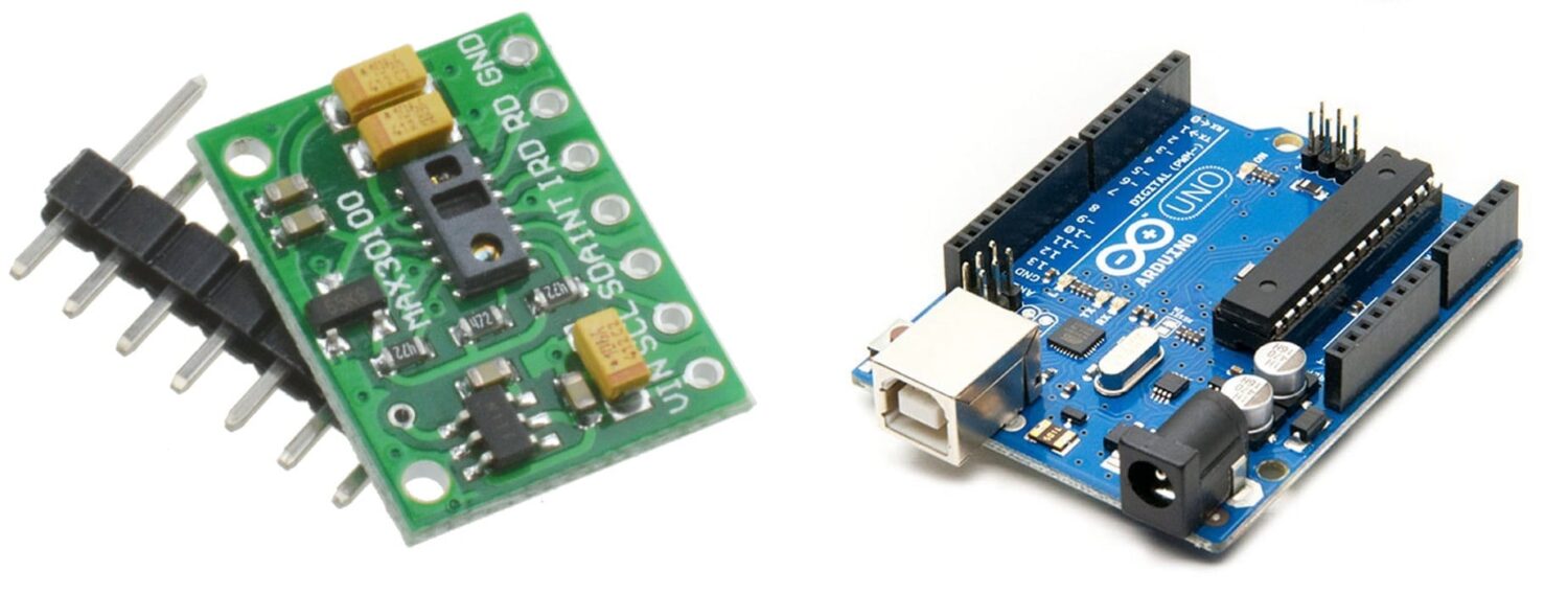
This tutorial is all about interfacing the MAX30100 pulse oximeter sensor with Arduino Uno. The sensor has the ability to measure blood oxygen and heart rate.
In order to measure the Heart beat in BPM and Oxygen level, the MAX30100 Oximeter is one of best devices to get this data. As it works on reflection of light, so just have to place finger on the light emitting from it to get your data from Arduino.
MAX30100 Oximter Description
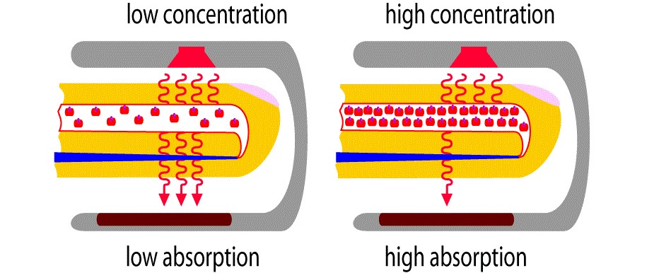
The oxygen percentage measures the haemoglobin concentration of the blood. This oxygen has a unique reflection when light falls on it. When we place the finger, it reflects the unique form of light back to the sensor absorber. The frequency of this light gives us the quantity of oxygen in the blood. Beams of light are passed through the finger to measure the level of oxygen present in the blood. There is a change in absorbing beams which help in reading the oxygen in the blood. The following figure helps in understanding how common oximeters work:
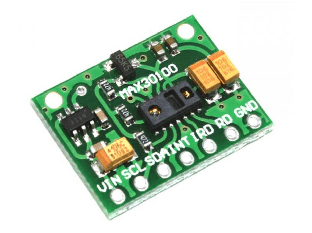
Pinout Of MAX30100
There are 5 pins present on the sensor namely VIN, GND, SCL, SDA, and INT. There is the Power pin that needs to connect with the sensor VIn. GND pin is connected with the ground pin. SCL is a clock pin that is connected to an A5 pin and SDA is connected to an A4 pin on Arduino Uno. The sensor contains two LEDs, a photodetector, and a low-noise analog signal processing unit to measure heart rate. The operating voltage for the sensor is between 1.8 volt and 3.3 volts.
| Sr. | MAX30100 Pin | Arduino Uno Pin |
| 1 | VIN | 3.3V |
| 2 | GND | GND of Arduino |
| 3 | SDA | Connected with A4 of Arduino pin |
| 4 | SCL | Connected with A5 of Arduino pin |
| 5 | INT | NOT Connected |
Technical working of MAX 30100 Pulse Oximeter and Heart-Rate Sensor
The sensor contains two LEDs. One has the capability of emitting red light whereas the other one emits infrared light. For measuring pulse rate, infrared light-emitting led is enough. In order to measure oxygen, both lights are necessary. When the heart contracts and blood is pumped throughout the body, the amount of oxygen in the blood increase hence the oxygen blood increases. On the contrary, when the heart relaxes, the amount of oxygenated blood also drops. By calculating the time between increase and decrease in the level of oxygen blood Pulse rate is measured. It is experimentally observed that oxygenated blood absorbs more infrared light than red light and, opposite to this behaviour, deoxygenate blood absorbs more red light as compared to infrared light. The sensor reads the values of absorption for both types of light and sends it to the microcontroller with the help of the I2C protocol.
What We Need?
As usual, I suggest adding from now to your favourite e-commerce shopping cart all the needed hardware, so that at the end you will be able to evaluate overall costs and decide if to continue with the project or remove them from the shopping cart. So, hardware will be only:
Step-by-Step Procedure
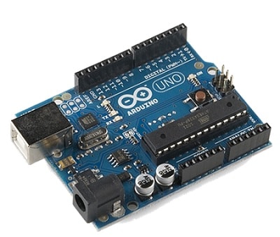
Wiring MAX 30100 with Arduino Uno
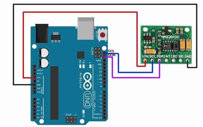
As shown in the image below, the sensor is connected with Arduino Uno. Please follow wiring that, according to Arduino Uno Pinout to make the connections.
Arduino PIN >> MAX30100 PIN:
3.3V>> VIN
SCL>> A5 or blue wire, both are SCL of Arduino
SDA >> A4 or follow pin wire
GND >> GND
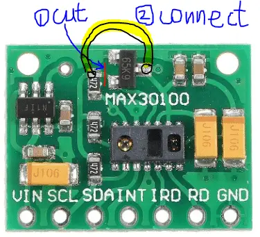
Technical Issue in Most of the PCBs of this Sensor
In MAX30100 there is an issue with the connection in the PCB. There is IC name “65K9” which, according to tests from web users, needs to be removed or bypassed. As shown in the picture, Following step 1, cut the PCB wire at the red line, and connect with a jumper by following the yellow line.
Prepare The Oximeter Code
Connect your PC to Arduino and open Arduino IDE. For the very first steps, you can refer to Connecting Windows PC with Arduino tutorial. You can get the .ino code from my download area with the following link:
We also need the MAX30100 library to get the project working. You can get it from the following link and install it according to Install Arduino Libraries: methods to add libraries with Arduino IDE tutorial:
Please find below a brief code description.
Oximeter Code Description
In the beginning, we define PIN. We use the A4 and A5 for the sensor pin where we connected the data for the oximeter sensor. Two libraries are included in the code in the first two lines.
#include <Wire.h>
#include "MAX30100_PulseOximeter.h"
In the third line, a variable name reporting period given the value of 1000 milliseconds which is equivalent to one second.
#define REPORTING_PERIOD_MS 1000We create an object name as pox using the line given below
PulseOximeter pox;In the next line, we declare a variable and give the initial value 0 to correctly manage reports.
uint32_t tsLastReport=0;Next, a function prints on the serial monitor “Beat” when it is detected.
void onBeatDetected()
{
  Serial.println("Beat!");
}
Now, in the setup function, the serial monitor initializes at a baud rate of 115200 and we print the “Initializing” notice on the serial monitor. Then in the next lines, a condition applies. “if(!pox.begin())” means that if the sensor is not properly connected or there is some sort of issue. If the sensor does not connect properly, then our code prints a “Fail” warning on the serial monitor. Otherwise, the code prints “Success” on the serial monitor. Then in the following lines, we call two functions. One function sets the led current and the other detects the beat.
void setup()
{
  Serial.begin(115200);
  Serial.print("Initializing pulse oximeter..");
  if (!pox.begin()) {
    Serial.println("FAILED");
    for (;;);
  }
  else {
    Serial.println("SUCCESS");
  }
  pox.setIRLedCurrent(MAX30100_LED_CURR_7_6MA);
  pox.setOnBeatDetectedCallback(onBeatDetected);
}
The loop function begins with a function call to get the values updated. Millis() function returns the time Arduino has taken since reset or start to the execution of this line. We calculate their difference and compared it with the variable “REPORTING_PERIOD_MS”. This condition provides the code execution when the time difference exceeds one second. This means that the code will print measures of heart rate and oxygen on the serial monitor every second.
void loop()
{
pox.update();
if (millis() - tsLastReport > REPORTING_PERIOD_MS) {
Serial.print("Heart rate:");
Serial.print(pox.getHeartRate());
Serial.print("bpm / SpO2:");
Serial.print(pox.getSpO2());
Serial.println("%");
tsLastReport = millis();
}
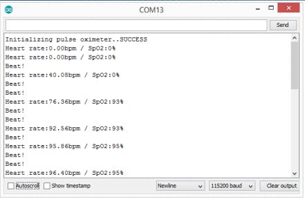
}Results
Finger placed on the sensor which is displaying on the serial monitor. Reflection of light is giving the results of oxygen and heartbeat. Please note that you have to open the serial monitor at a 115200 baud rate.
Enjoy!
Please find more tutorials on Arduino in peppe8o Arduino archives.
Umar Jamil
For any queries and help for work, please contact me at:
Whatsapp: +92-346-661-7017
Email: umarjamil0007@gmail.com

I'm an Electronic Engineer, well-skilled to solve the issues of hardware and software. I do have laboratory which contains unlimited sensors and modules for testing the working. Also, I am experienced in Arduino programming, Android mobile application, microcontroller programming, IOTs and embedded projects. I provide services to control, realize the sensor data in the Mobile Application. For any queries and help for work Contact: Whatsapp:+92-346-661-7017 Email: umarjamil0007@gmail.com
![]()


