
Last Updated on 2nd September 2023 by peppe8o
In this tutorial, I’ll show you how to build a voltage meter with Arduino Uno, able to deal with a 0-30V range. This tutorial provides the coding, wiring diagram and component list.
To measure a range from 0V to 30V, a voltage divider circuit enables you to linearly reduce the input to 5V and create a voltage meter with Arduino.
Important note: In order to avoid your microcontroller breaking, you must be aware of the max current that Arduino Uno R3 can drain. Generally, the microcontroller can support up to 40mA for each port and a maximum of 200mA for the whole board, but a deeper explanation can be found on Arduino Pin Current Limitations page.
Introduction
When utilizing the 5V analogue reference voltage, analogue inputs can monitor DC voltage between 0 and 5V. The range extends by employing two resistors to produce a voltage divider. The voltage divider reduces the measured voltage to fit within the analogue input range of the Arduino. The actual voltage measure computes using code from the Arduino sketch.
Working Phenomena
We’ll build a voltage divider circuit to extend the 5V range.
A voltage divider consists of a 15K resistor (R2) and a 3K resistor (R3) circuit, able to enhance the range of the Arduino Board’s analogue input up to 30V. This divider reduces the measuring input voltage to the analogue input range of the Arduino Board. If you’re dealing with batteries or want to construct your own adjustable power source, you’ll need to measure voltages.
It’s quite easy to measure voltages using an Arduino. Multiple analogue input pins of the Arduino connect to an analogue-to-digital converter (ADC). The Arduino ADC is a ten-bit converter with a range of 0 to 1023 as the output value. The analogRead() method uses to get this value. You can simply determine the voltage existing at the analogue input if you know the reference voltage (in this example, 5V).
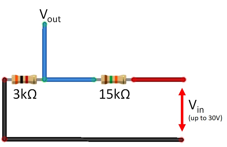
Important Note: If you need to change the voltage limit, you have to take different values of the R1 (3k Ohm) and R2 (15k Ohm) resistors, by calculating the resistor’s value from the following equation:
max Vin = (R1+R2) x 5V / R1
This equation makes it possible to check that the voltage reached at the Arduino’s analogue pin is lower or equal to 5V. But you must also check that the applied current is compatible with the Arduino board as warned at the beginning of this tutorial.
What We Need
As usual, I suggest adding from now to your favourite e-commerce shopping cart all the needed hardware, so that at the end you will be able to evaluate overall costs and decide if to continue with the project or remove them from the shopping cart. So, hardware will be only:
Check hardware prices with the following links:


Step-by-Step Procedure
Wiring Diagram of Circuit with Arduino
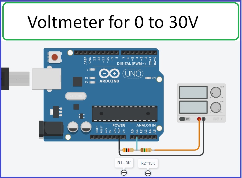
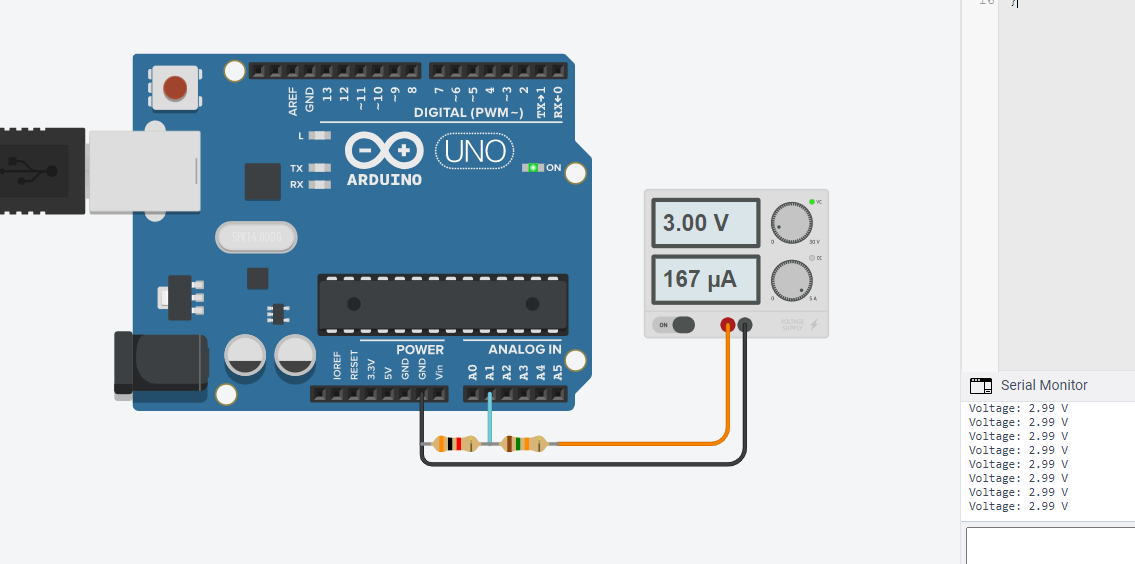
In the circuit, a voltage divider is composed and deals with the 0-5V for analogue pin A1 of the Arduino Uno. As shown in the image below, we also connect a power generator with the circuit in order to simulate a voltage to be confirmed from Arduino Uno reading. Please follow the wiring that presents in the picture, according to Arduino Uno Pinout:
Get the code from the link
Connect your PC to Arduino and open Arduino IDE. For the very first steps, you can refer to Connecting Windows PC with Arduino tutorial. You can get the .ino code and libraries from my download area with the following link:
Code Explanation
Section 1: We define a float variable to store the voltage value. In the setup, we set the serial monitor baud rate to 9600. We also configure the analog pin A1 as input to take the circuit’s value.
float voltage = 0.0f;
void setup()
{ Serial.begin(9600);
  pinMode(A1, INPUT);
}
Section 2: In the loop, an analogue voltage is read from the A1 pin and its multiplied by the step per millivolt value of 0.0293255. For Arduino Uno, the resolution is 10 bits which results in 10^10 is 1023. For one millivolt, the voltage generated at the analogue pin is 0.0293255. After that voltage displays on the serial monitor through serial command.
void loop()
{
  // Convert from 0-1023 range to 0-30V range
  // (.0293255  = 30.0 / 1023)
  voltage = (analogRead(A1) * 0.0293255);
  Serial.print("Voltage: ");
  Serial.print(voltage);
  Serial.println(" V");
  delay(100); // Wait for 100 millisecond(s)
}
Results
To test the results, we apply a generated 3V current and we’ll check what the analog port from Arduino is reading (from the serial monitor). This circuit can measure voltage in analogue form from 0 to 30 V of any value.
What’s Next
Please find more tutorials on Arduino in peppe8o Arduino archives.
Enjoy!
Umar Jamil
For any queries and help for work, please contact me at:
Whatsapp: +92-346-661-7017/ Link
Email: umarjamil0007@gmail.com

I'm an Electronic Engineer, well-skilled to solve the issues of hardware and software. I do have laboratory which contains unlimited sensors and modules for testing the working. Also, I am experienced in Arduino programming, Android mobile application, microcontroller programming, IOTs and embedded projects. I provide services to control, realize the sensor data in the Mobile Application. For any queries and help for work Contact: Whatsapp:+92-346-661-7017 Email: umarjamil0007@gmail.com
![]()


What happens if you reverse the polarity?
Hi Vik. In the best case, Arduino will read a 0V input (when the load has been inverted). There’s the possibility that the inverse polarity could stress the internal resistors of your microcontroller. The R1 resistor in the picture should offer you a basic protection from this, but adding a protection diode before the PINs should give you a safer design