Last Updated on 13th April 2024 by peppe8o
In this tutorial, I will show you how to use a relay with Raspberry PI Pico. I will give you a simple usage example with a DC water pump.
When your project includes devices with high current requirements, a relay with Raspberry PI Pico can save your microcontroller from burning its circuits and enable a world of new sensors or motors to connect
How Relays Work
Relays are electromagnetic devices that use low-power input to control high-power loads. They can act like a current switch or a “slow” amplifier. I’m using the term “slow” for the amplifier as they have a very high response time (we’re talking less than one second) compared to other amplification solutions.
Relays are required to avoid the controlling circuit (or microcontroller) from burning when the load requires high current values that the controlling circuit can’t deal with. With the relays, your controlling logic becomes simpler and cheaper, without the need to design and deploy a high-power circuit also for the controlling logic.
An intuitive picture of how basically a relay works is provided by Wikipedia. In the following picture, the left side is the low-power circuit (our microcontroller), while the right side shows a simple high-power circuit with a bulb and a power generator (G). At the centre, the relay has an electromagnetic coil that controls a simple switch.
When a voltage applies to the low-power circuit, the coil generates a magnetic force that closes the high-power circuit, activating it. There’s no direct contact between the low power side and high power side as the coil performs the isolation:
Of course, this is a really simplified model of how the relay works, but it is a good experiment for schools in order to get the relay basics understood, even if you will be able to hear the “click” at the relay closing even in the newest relays for hobbyists.
The most common relay usage is in projects requiring just to switch on or off a bulb, a water pump or activating motors.
Modern DYI Relay
Modern 5V relays for Raspberry PI Pico (and, generally, for microelectronics projects) come with small-size packaging. They usually also include a shield: a base PCB (printed circuit board) able to provide additional protection to the input and LEDs visually showing if the relay is closed or open.
The common 5V relay shield pinout includes 3 input PINs and 3 output PINs:
| PIN | Function |
|---|---|
| Vcc (input) | Input power reference (3V3OUT) |
| GND (input) | Ground power reference |
| IN (input) | Input trigger signal to control the relay |
| NO (output) | Normally Open output |
| COM or Middle Pin or C (output) | COMmon output, it usually goes to one of the 2 poles of our load |
| NC (output) | Normally Closed output |

While the input PINs are quite intuitive, it can be interesting to understand the output ones.
The COM is the relay port connected to the part that physically switches inside the relay. When the relay is off, the COM remains connected to the NC (Normally Closed) PIN. When the relay is triggered on, the COM port leaves the NC and moves to close the NO (Normally Open) PIN. In a few words, this gives us 2 use options:
- if our project needs to activate the output on trigger and deactivate it without trigger, then we should use the COM and the NO ports. This configuration better suits the need for projects needing to keep the output load deactivated for most of the time and activate it for a relatively small time.
- if our project needs to activate the output without trigger and deactivate it on trigger, then we should use the COM and the NC ports. This configuration better suits the need for projects needing to keep the output load activated for most of the time and power off it for a relatively small time.
An important thing to consider, before blaming your relay for working at the contrary compared with the expected results, is that many relay work with “Low Level Trigger“. This means that when the IN port goes low, the relay is activated, when the IN port goes high, the relay is deactivated.
Current Considerations with Relay and Raspberry PI Pico
The use of a Relay can save our Raspberry PI Pico from “doing the dirty work”. But common relays are designed for general purposes and don’t take into account the specific thresholds of Raspberry PI Pico.
During my tests with the configuration, that I’ll show you in the following chapters, I measured that my relay input drains around 45mA from the Raspberry PI Pico PIN, when the trigger is active. It reduces to around 1mA when the trigger is not active.
It’s not a huge value compared to the microcontroller capabilities (50mA limit to the sum of all GPIO outputs and 10mA for each GPIO) and the Raspberry PI Pico can probably deal without problems with these values if applied for a very limited time (for example, the time required to water a plant that can be around a few seconds). For longer needs, using an amplification circuit at the Raspberry PI Pico output (for example with a simple transistor) will save your microcontroller from burning.
The Relay and Raspberry PI Pico Test
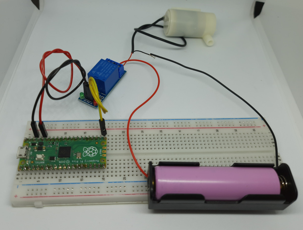
In order to get an example of how the Relay and Raspberry PI Pico work together with MicroPython, I will create a simple circuit with the Raspberry PI Pico triggering a relay shield. My load will be a DC water pump, with the related power generator being a 18650 battery. This is similar to the one I used in my How to power Raspberry PI Pico with Solar Cells tutorial.
Of course, this tutorial will also work with the Raspberry PI Pico W, which allows creating your DIY smart relay.
What We Need
As usual, I suggest adding from now to your favourite e-commerce shopping cart all the needed hardware, so that at the end you will be able to evaluate overall costs and decide if to continue with the project or remove them from the shopping cart. So, hardware will be only:
- A common computer (maybe with Windows, Linux or Mac). It can also be a Raspberry PI Computer board
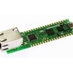
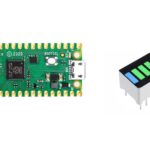
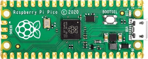
- Raspberry PI Pico microcontroller (with a common micro USB cable)
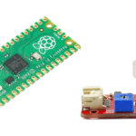
- 5V Relay Shield
- breadboard (optional)
- dupont wirings
- DC water pump or any load
- 18650 battery with 18650 case
Step-by-Step Procedure
Relay and Raspberry PI Pico Wiring Diagram
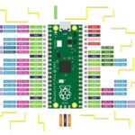
Please prepare the wiring as in the following picture, according to the Raspberry PI Pico pinout:
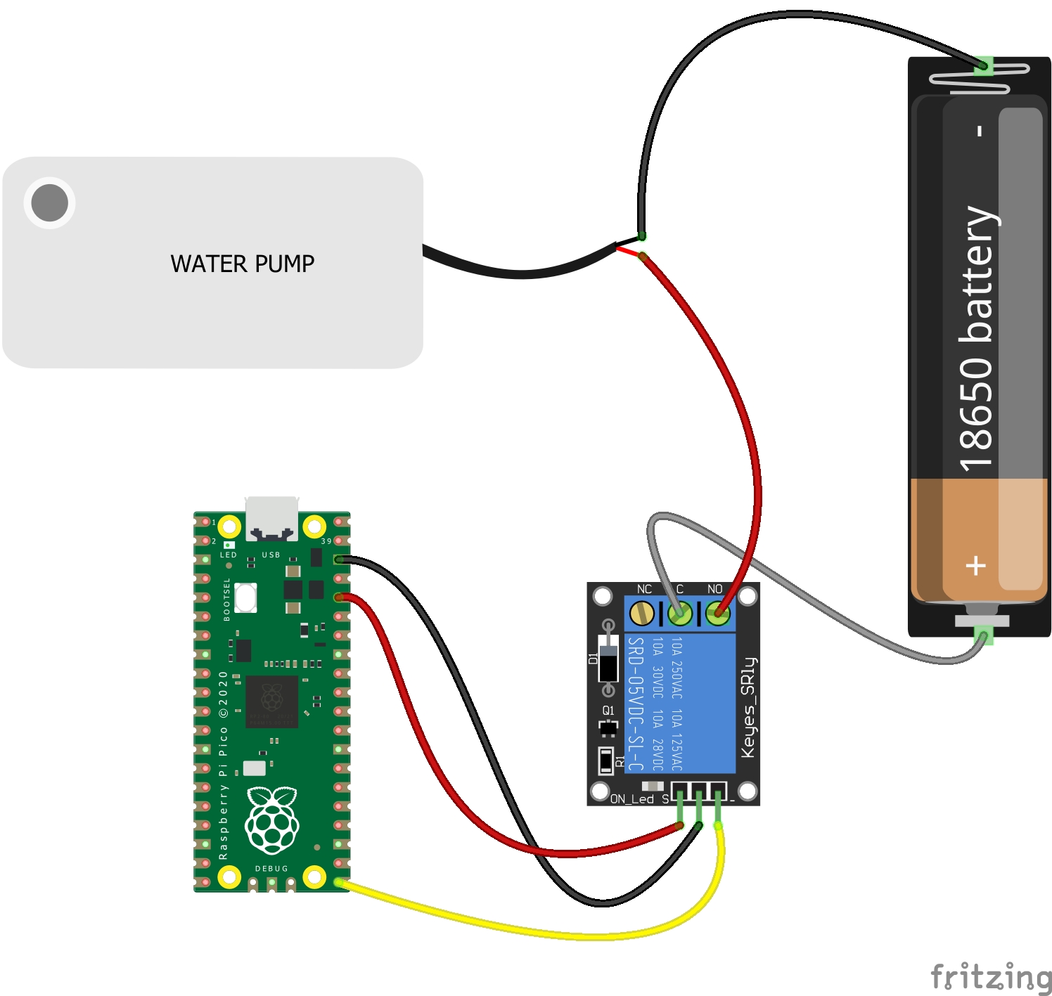
The following table will give you help with the connection of the parts, with the single lines representing the bridged parts:
| RPI Pico | Relay Shield | Water Pump | Battery |
|---|---|---|---|
| GND | GND | ||
| 3v3(out) | Vcc | ||
| GP16 | IN | ||
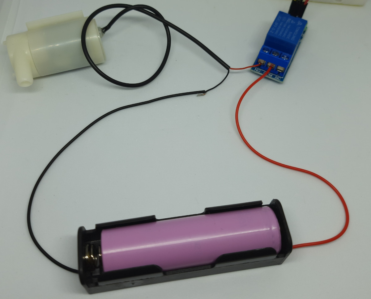
| COM | Positive Pole | ||
| NO | Positive Pole | ||
| Negative Pole | Negative Pole |
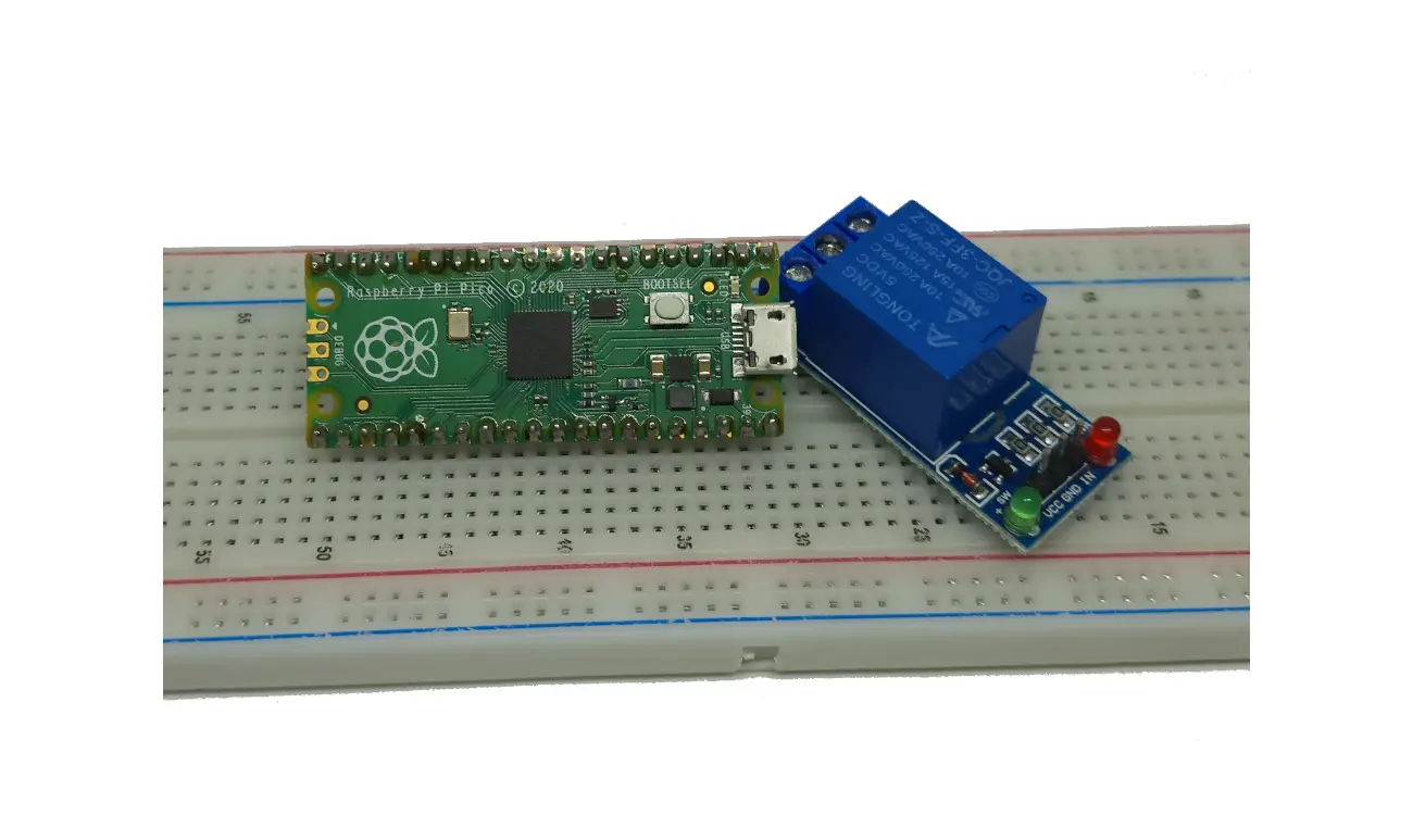
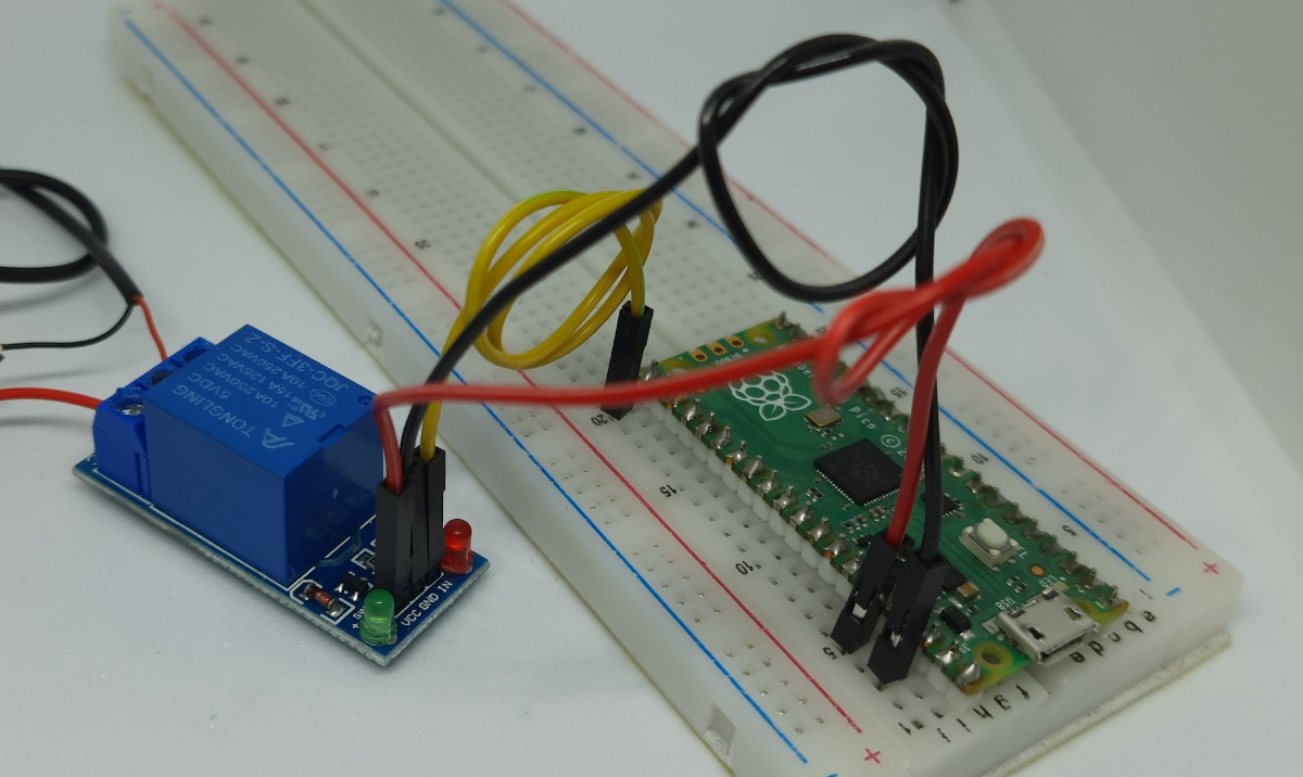
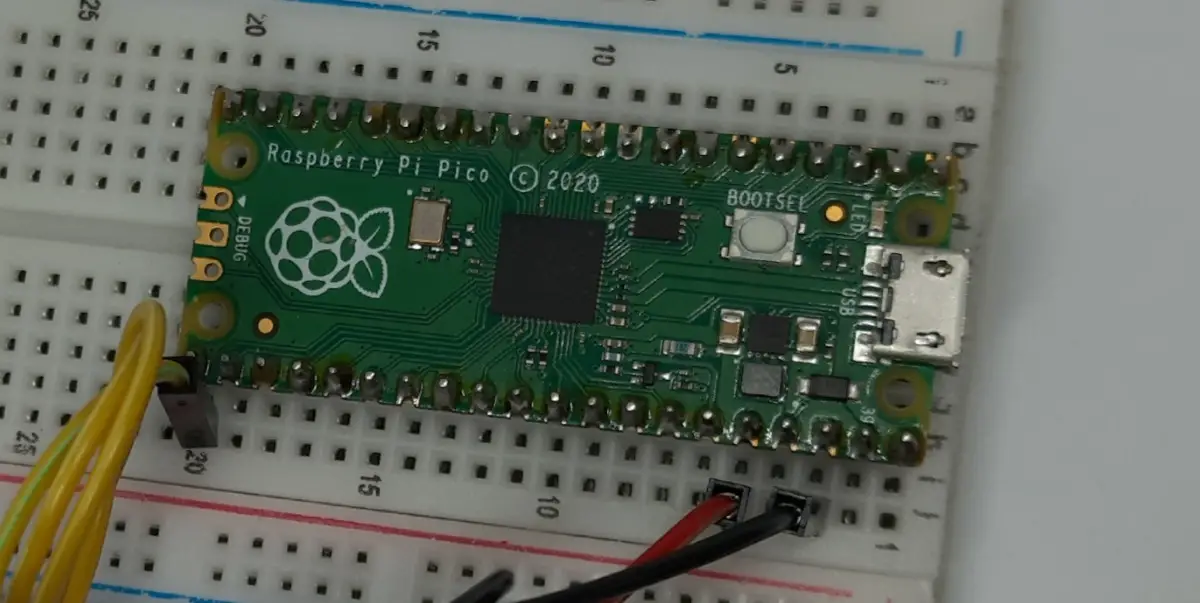
Please find below some pictures from my wiring:
MicroPython Code to Test the Relay with Raspberry PI Pico
Connect RPI Pico to Thonny (you can refer to my tutorial about the First steps with Raspberry PI Pico).
Please download the code from the following link and save it to your Raspberry PI Pico storage:
The following lines will explain the code line by line.
Before this explanation, please remember that the relay (at least the one I’m testing) works with a Low level Trigger. This means that by sending to the relay from Raspberry PI Pico PIN a low (o) input I will activate the relay. On the other side, by sending a high (1) input, I will deactivate the relay. Also, please note from the wiring diagram and the pictures that I’m using the relay “Normally Open” port.
In the begin, we import the required modules. Please note that only the machine module is required for its Pin function. I will use the sleep function only to make the relay active for enough time to see it in this state:
machine import Pin
from time import sleep
Here I add a reference for the Raspberry PI Pico PIN where I connected the relay input. Having this declared as a variable makes the code clean and easy to edit for any need to change the wiring PIN:
relay_pin = 16
We now create the relay object, which is just a Pin object set to output:
relay = Pin(relay_pin, Pin.OUT)
In the following lines, you will take another proof that I really love building code with custom functions. They make again the code really clear and easy to customize. The first function, named “relay_on”, will trigger the relay to activate its output by bridging the output “COM” port to the output “NO” port. This will result in the current flowing in the output circuit. We get this by simply putting low the Raspberry PI Pico port connected to the relay IN pin:
def relay_on():
    relay.value(0)
Similarly, switching off the relay requires only setting the Raspberry PI Pico output to high:
def relay_off():
    relay.value(1)
The final code is just the simplest test. The Raspberry PI Pico triggers the relay to on by calling the relay_on() custom function. The sleep(5) line will keep this state for 5 seconds, so the relay will stay switched on for 5 seconds. Finally, the relay_off() just triggers off the relay:
relay_on()
sleep(5)
relay_off()
Running the relay-pico.py Script
Run this script in your Thonny IDE (F5) and you will start seeing your output load running for 5 seconds and then shutting off.
Final Suggestion
At the Raspberry PI Pico boot, its output PINs could have an undefined state. When reusing this code for your projects I suggest starting your main program (after the custom functions definition) with a relay_off() call. This will assure you that you are starting your program with a controlled and defined state.
What’s Next
Interested to do more with your Raspberry PI Pico? Try to look at my Raspberry PI Pico tutorials for useful and funny projects!
Enjoy!

Open source and Raspberry PI lover, writes tutorials for beginners since 2019. He's an ICT expert, with a strong experience in supporting medium to big companies and public administrations to manage their ICT infrastructures. He's supporting the Italian public administration in digital transformation projects.
![]()
![]()
![]()
![]()
![]()
![]()
![]()