
Last Updated on 22nd March 2024 by peppe8o
In this tutorial, I’m going to show you how to wire, configure and calibrate a magnetometer (HMC5883L) with Raspberry PI computer boards. Please note that if you want to use the Raspberry PI Pico instead, you can refer to my Magnetometer Compass with Raspberry PI Pico: GY-271 HMC5883L wiring and use with MicroPython tutorial.
HMC5883L Main Features
When you need to keep your Raspberry PI aware on where is the North, surely an HMC5883L magnetometer is better that instructing the RPI to look at North Star 🙂
This module features are also already referenced in the tutorial for RPI Pico (see link above).
But it’s still really important to remind that the market is also full of the QMC5883L module magnetometer. From what I know, this should make the same job but has a different hardware logic, so requiring a different code (and the code within this guide hardly will work for QMC5883L).
The HMC5883L is a multi-chip module able to measure magnetic sensing and communicating by the I2C digital interface. The module works with a low voltage supply (from 2.16 to 3.6V) and also has a low power consumption (100 μA). So we’ll connect it to the 3,3V power GPIO of our Raspberry PI.
HMC5883L has a 1° to 2° degrees heading accuracy, which is enough for a wide number of applications. It also allows setting its internal gain to increase resolution with a 3-bit gain control register. But increasing gain also increases noise effects.

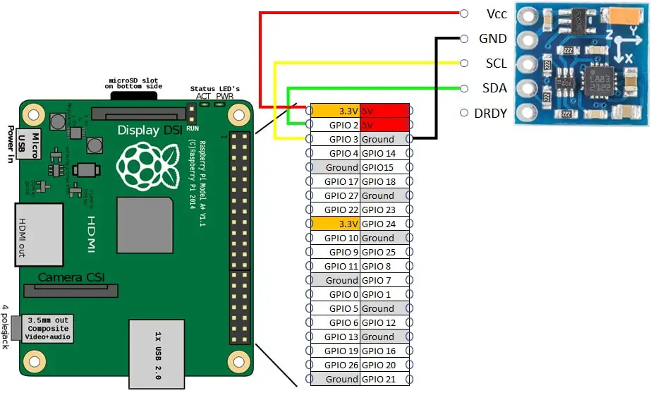
The HMC5883L pinout has 5 PINs:
- Vcc -> common positive PIN for power supply, goes to the 3,3V PIN from Raspberry PI Pico
- GND -> common ground pin, goes to one of GND PINs from Raspberry PI Pico
- SCL -> Serial clock pin for I2C communication
- SDA -> Seria data pin for I2C communication
- DRDY -> Data Ready, Interrupt Pin. It is a PIN warning the master device when data are ready in registers to be read. It is optional and communication as well as readings work also without using this PIN.
More details on the HMC5883L chip are available from HMC5883L_3-Axis_Digital_Compass_IC datasheet pdf file available from Adafruit pages.
Please, be aware that this tutorial is intended for the Raspberry PI computer boards, as the Raspberry PI Pico is a microcontroller and its procedure can be found in my link at the beginning of this post.
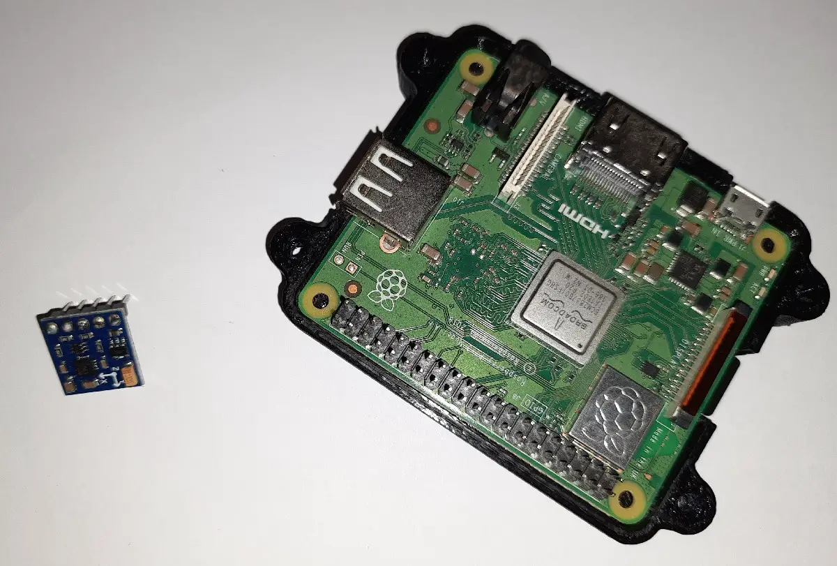
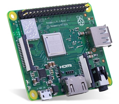
For this post, I’m going to use a Raspberry PI 3 Model A+. But this tutorial will work with any Raspberry PI computer.
What We Need
As usual, I suggest adding from now to your favourite e-commerce shopping cart all the needed hardware, so that at the end you will be able to evaluate overall costs and decide if to continue with the project or remove them from the shopping cart. So, hardware will be only:
- Raspberry PI 3 Model A+ (including proper power supply or using a smartphone micro usb charger with at least 3A) or newer Raspberry PI Board
- GY-271 HMC5883L module
- breadboard (optional)
- dupont wirings
Step-by-Step Procedure
Wiring Diagram
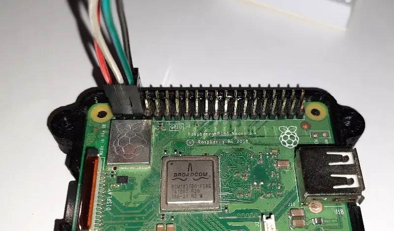
Please prepare cabling according to the following picture. With other Raspberry PI computers, you can refer to my Raspberry PI Zero Pinout as all the 40-pin versions have the same configuration.
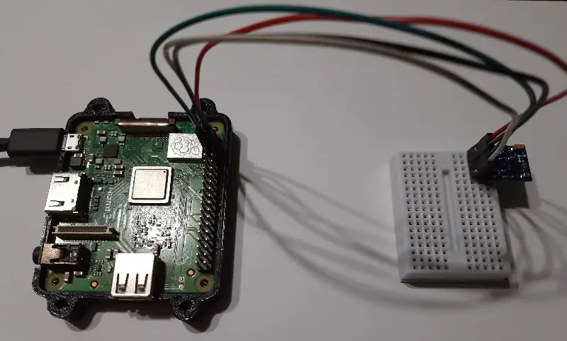
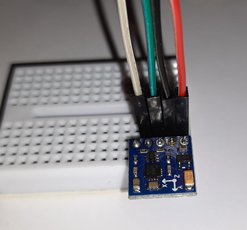
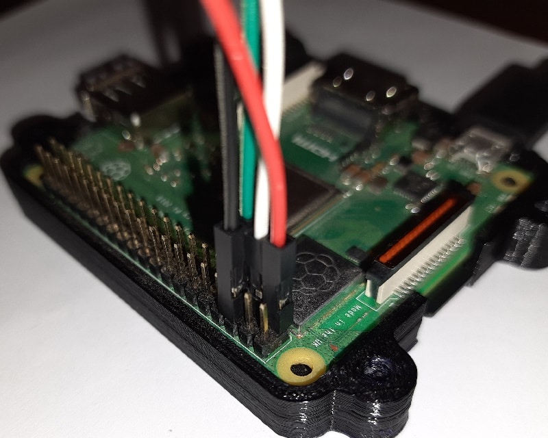
Please find below some pictures with my cabling details:
Install Operating System and Required Packages
Firstly, please install your OS. You can use Raspberry PI OS Lite (for a headless, performing OS) or Raspberry PI OS Desktop (if you need a Desktop environment). In the second case, you will operate from its terminal.
Make your OS up to date. From the terminal, please use the following command:
sudo apt update -y && sudo apt upgrade -yRPI.GPIO should be already installed (otherwise, you can get it installed with the command “sudo apt install python3-rpi.gpio”). Install required packages. smbus2 will be get with the pip3:
sudo apt install python3-pip i2c-tools
pip install smbus2
Enable I2C Interface
We need to enable the I2C interface to get our HMC5883L device working and communicating. From terminal:
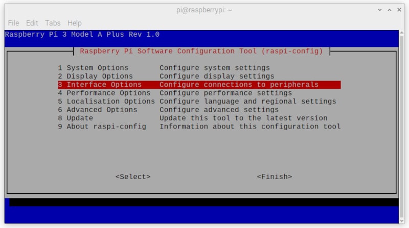
sudo raspi-configIn the first screen, please select “Interface Options”:
Then move to I2C option:

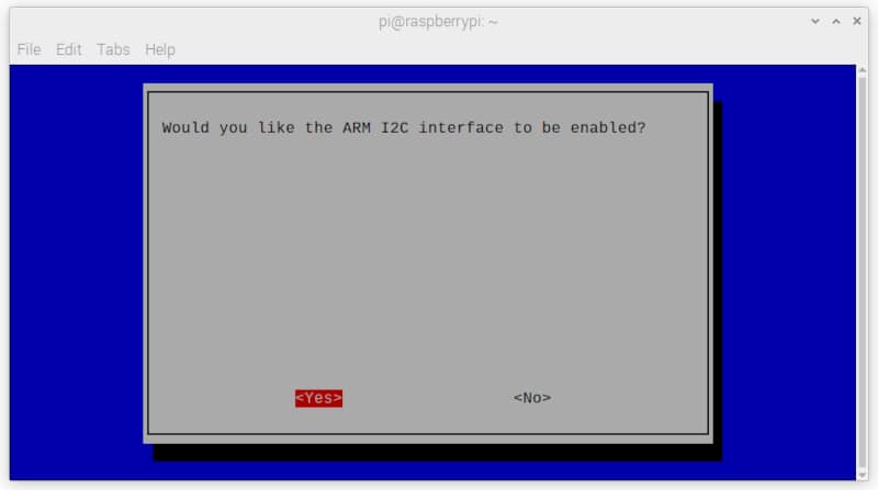
You will be asked if you want to enable the I2C interface. Of course, select “yes”
A confirmation will show up:
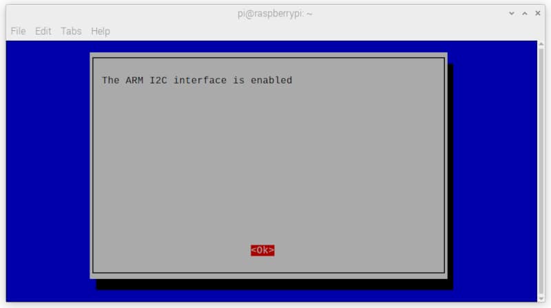
After giving the “OK”, you will be back to raspi-config home and you can exit from here by selecting “Finish”
Check that your device is correctly answering the i2c detection. From terminal, use the “i2cdetect -y 1” command to get a result similar to the following:
pi@raspberrypi:~ $ i2cdetect -y 1
     0  1  2  3  4  5  6  7  8  9  a  b  c  d  e  f
00:                         -- -- -- -- -- -- -- --
10: -- -- -- -- -- -- -- -- -- -- -- -- -- -- 1e --
20: -- -- -- -- -- -- -- -- -- -- -- -- -- -- -- --
30: -- -- -- -- -- -- -- -- -- -- -- -- -- -- -- --
40: -- -- -- -- -- -- -- -- -- -- -- -- -- -- -- --
50: -- -- -- -- -- -- -- -- -- -- -- -- -- -- -- --
60: -- -- -- -- -- -- -- -- -- -- -- -- -- -- -- --
70: -- -- -- -- -- -- -- --
The “1e” is the address of HMC5883L device in the I2B bus. If you get a different address, please note that your chip is probably different (it may be a QMC5883 digital compass: same function but different chip) and this tutorial could not work with it.
Get HMC5883L libraries
We need to get the libraries that will make our code simpler. From Github, they are available at https://github.com/peppe8o/rpi-peppe8o/tree/main/python/hmc5883l. OR you can get them from my download area directly in your Raspberry PI, with the following terminal commands:
wget https://peppe8o.com/download/python/hmc5883l/i2c_core.py
wget https://peppe8o.com/download/python/hmc5883l/i2c_hmc5883l.py
These files must be saved in the same folder of the following scripts or into your default python library path.
Please note that the i2c_hmc5883l.py file includes the following code lines:
# Correction to be set after calibration
xs=1
ys=1
xb=0
yb=0
These are corrections to be set after a first run with the calibration script. These values are the default ones and need to stay set in this way for each calibration run.
Set Your Location Declination
Before starting, we need to keep track in our library about the Declination, as explained in my Magnetometer Compass with Raspberry PI Pico: GY-271 HMC5883L wiring and use with MicroPython tutorial.
So, to keep our compass pointing to the Geographic north we need to add a correction that manages the difference between the 2 Norths and depends on our location. To get this, which is composed of 2 values (declination and inclination), please use the free online service available at https://www.magnetic-declination.com/, point it in your position and keep their degrees. The following picture shows what are mine results for my position (Rome):
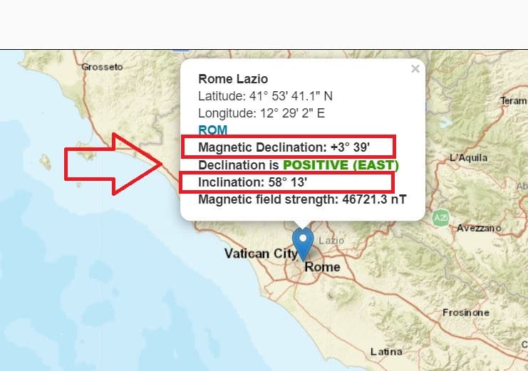
With this result, my declination setup will be “(3, 58)” instead of the default “(0, 0)”.
Calibrate the HMC5883L magnetometer
Download the calibration script:
wget https://peppe8o.com/download/python/hmc5883l/hmc5883l_calibrate.pyThis script will help you in defining the calibration corrections so that your measured heading values will be far nearer to real ones.
Before running, open it to edit:
nano hmc5883l_calibrate.pyAnd identify the declination setup row:
i2c_HMC5883l.set_declination(0, 0)Set it according to your declination. For example, mine one will be:
i2c_HMC5883l.set_declination(3, 58)Close and save.
Place your hmc5883l onto a plain surface, we’ll need to rotate it at least twice for calibration, by performing 360-degree rotations. Run the calibration script from the terminal with the following command:
python3 hmc5883l_calibrate.pyYour terminal will start showing the magnetic field measured, also keeping the min and max value for both X and Y axes. With the script running, please rotate slowly the hmc5883l on the plain surface (so that the “X” axis printed on the device can do at least one entire round between north, est, south and west in whatever order.
After this, stop the script by pressing CTRL+C. The final calibration result will be calculated and shown:
...
Xmin=-556.15; Xmax=172.52; Ymin=-488.05; Ymax=199.76
(27.24, 115.77, -345.04)
Xmin=-556.15; Xmax=172.52; Ymin=-488.05; Ymax=199.76
(27.24, 115.77, -345.04)
Xmin=-556.15; Xmax=172.52; Ymin=-488.05; Ymax=199.76
^C
Got ctrl-c
Calibration corrections:
xs=1
ys=1.0594059405940595
xb=191.81499999999997
yb=144.14499999999998
Edit the i2c_hmc5883l.py
nano i2c_hmc5883l.pyAnd change the correction values according to the calibration results:
...
class HMC5883(object):
    # Correction to be set after calibration

    xs=1
    ys=1.0594059405940595
    xb=191.81499999999997
    yb=144.14499999999998

    # Define registers values from datasheet

    ConfigurationRegisterA = 0x00
    ConfigurationRegisterB = 0x01
    ModeRegister = 0x02
...
Get and Run hmc5882l Usage Script
Download the example script which shows how to use the libraries:
wget https://peppe8o.com/download/python/hmc5883l/use-hmc5883l.pyAgain, open the file for editing:
nano use-hmc5883l.pyand set your declination. mine one will be:
i2c_HMC5883l.set_declination(3, 58)Close and save.
The code is really simple. First of all, required libraries are imported
from i2c_hmc5883l import HMC5883
from time import sleep
Then we set bot the gauss value and declination for the HMC5883L object:
i2c_HMC5883l = HMC5883(gauss=1.3)
i2c_HMC5883l.set_declination(0, 0)
The final loop prints read values. At each reading, a sleep of 1 second will slow a bit the reading/printing to make it visible for human reading:
while True:
   print(i2c_HMC5883l.get_heading())
   sleep(1)
Run the script:
python3 use-hmc5883l.pyand you will start looking at measured value:
pi@raspberrypi:~ $ python3 use-hmc5883l.py
(103, 35)
(103, 29)
(103, 52)
(132, 8)
(153, 13)
(85, 43)
(41, 60)
(24, 8)
(42, 30)
...
The first value is the degree, while the second one is the minutes.
Final Thoughts
Also in this tutorial (like the same one for Raspberry PI Pico), the calibration process involves only the X and Y axes. So any help on how to mathematically involve also the Z axis is really welcome and I will update the code. Anyway, for horizontal plane measurements, it will work giving you a reliable angle.
What’s Next
Now that you know what are the Raspberry PI Pico PINs, you can use my Raspberry PI Pico tutorials for useful and funny projects!
Enjoy!

Open source and Raspberry PI lover, writes tutorials for beginners since 2019. He's an ICT expert, with a strong experience in supporting medium to big companies and public administrations to manage their ICT infrastructures. He's supporting the Italian public administration in digital transformation projects.
![]()
![]()
![]()
![]()
![]()
![]()
![]()


I noticed the guass value differs in the calibration script and in the i2c_hmc5883l script. Should those values match? What effect does adjusting those values have?
Great comment, Evan. Thank you.
The Gauss value should be the same both during calibration and usage script. I’m going to correct and align both to one value
Hi. I’m using bus 3 instead of bus 1 and was wondering where i can change the code. right now i’m getting an I/O error
Hi Amie,
I’ve never tested different I2C buses on Raspberry PI. From what I can read on the web (but never tested), you should enable the new I2C buses from the config.txt file and then reboot. Then, you should try if the Raspbrry PI can detect it with the
sudo i2cdetect -y 3. I must suppose you already did these steps and worked for you.Now, from Raspberry PI, when you scan the I2C bus for the remote device addresses, what address do you read?