Last Updated on 21st January 2024 by peppe8o
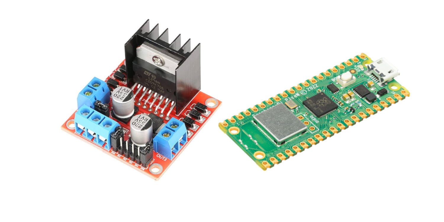
This tutorial will show you how to drive motors with L298N and Raspberry PI Pico, describing how this dual H bridge motor driver works, how to connect it to the Raspberry PI Pico and how to use it with MicroPython.
This module is a great alternative to the L293D chip, as it can drive higher current. But the working principle is the same, so you can check my L293D and DC Motor with Raspberry PI Pico tutorial to get more info about controlling motors with PWM (Pulse
How the L298N Works
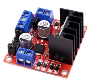
This interesting module is a great choice for those approaching drone/robot projects (to drive, for example, 8520 DC motors or NEMA-17 motors), or any project involving motors requiring a lot of current.
L298N Specs
The main features are listed below:
- Input Voltage: 3.2V~40Vdc
- Power Supply: DC 5 V – 35 V
- Peak current: 2 Amp
- Maximum power consumption: 20W
- Storage temperature: -25 ℃ ~ +130 ℃
- Size: 3.4cm x 4.3cm x 2.7cm
More info is available from https://www.handsontec.com/dataspecs/L298N%20Motor%20Driver.pdf
L298N Pinout
The L298N module has a particular diagram which becomes useful if well understood:
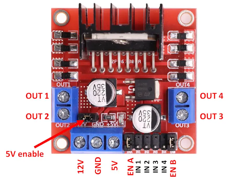
- Power PINs:
- 12V: this is where you must connect the positive pole of your battery. This will provide current to the module and your motors
- GND: here comes the classic ground reference (still from the battery)
- 5V enable: this PIN controls the 5V logic to output or input. I will show it in the following list point:
- 5V: this is an interesting PIN, as it can work both as input and output power PIN. There are 3 use cases:
- If you want to power the L298N (and motors) with a 5V power input, you can remove the “5V enable” jumper (keeping disconnected the 12V input PIN) and everything will take current from the 5V PIN.
- If you want to use an external power source able to provide up to 12V, you can connect this power source to the 12V PIN and keep the “5V enable” jumper connected. In this way, the 5V becomes an output PIN where you can take, for example, a power source for your microcontroller and power your Raspberry PI Pico
- If you want to use an external power source able to provide a higher power input, you can connect this power source to the 12V PIN but you must remove the “5V enable” jumper as it will damage the L298N internal power regulatory
- OUT PINs: these are the PINs where you can connect your DC motors. Consider OUT1 and OUT2 as the “A Group”, OUT3 and OUT4 as the “B Group”. Usually, if you need to use DC motors able to run both in clockwise and counter-clockwise directions, you must use an OUT group (OUT1/2 or OUT3/4) to control the 2 wires coming from your motors, so resulting in 2 total motors controlled. If you can manage your motors to run only in 1 direction, then you can use the 4 outputs driving 4 different motors, with their wires coming both to the related OUT (the first wire) and their second wires going directly to the GND connector. This layout offers you the ability to control more motors, but you need to check the current required from the DC motors to avoid overcoming the 2A and 20W limits of the L298N module.
- IN 1/2/3/4 PINs: each of these PINs controls the current driving the related OUT PIN. So, IN1 controls OUT1, IN2 controls OUT2, and so on.
- EN A/B PINs: these PINs enable the OUT groups labelled as above described. Usually, they come with jumpers fixing the EN PINs to high. You can remove these jumpers if you need to control the EN signal from your Raspberry PI Pico: if you put high the ENA, it will enable the OUT1 and OUT2 outputs. If you put high the ENB, then you will enable the OUT3 and OUT4 outputs.
L298N Working Principle
The PINs above describe work in a way that can be summarized as shown in the following picture:
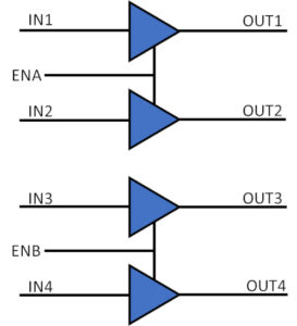
As the speed of many DC motors can be controlled via PWM signals, with this schema you can apply your PWM input from the ENA/B PINs or the single IN1/2/3/4 PINs, according to your project needs.
Moreover, you can use the jumpers coming with the L298N module to keep ENA and/or ENB always enabled, in case your project doesn’t need to disable them. In this way, you’ll reduce the number of wires required to drive the motors.
The table below gives you a matrix showing what are the operation modes for the “A” group (with the ENA, IN1, IN2, OUT1, and OUT2 PINs). the “B” group works similarly:
| ENA | IN1 | IN2 | OUT1 | OUT2 | 2 wires motor (connected to OUT1 + OUT2) | 1 wire motor (connected to OUT1 + GND) | 1 wire motor (connected to OUT2 + GND) |
|---|---|---|---|---|---|---|---|
| o | any | any | 0 | 0 | off | off | off |
| 1 | 0 | 0 | 0 | 0 | off | off | off |
| 1 | 0 | 1 | 0 | 1 | rotating | off | rotating |
| 1 | 1 | 0 | 1 | 0 | rotating (opposite direction) | rotating | off |
| 1 | 1 | 1 | 1 | 1 | off | rotating | rotating |
What We Need
As usual, I suggest adding from now to your favourite e-commerce shopping cart all the needed hardware, so that at the end you will be able to evaluate overall costs and decide if to continue with the project or remove them from the shopping cart. So, hardware will be only:
- A common computer (maybe with Windows, Linux or Mac). It can also be a Raspberry PI Computer board
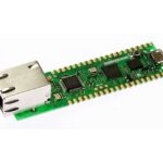
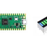
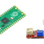
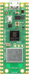
- Raspberry PI Pico microcontroller (with a common micro USB cable)
- L298N Driver
- DC motor
- Dupont wirings (optional)
- Breadboard
Step-by-Step Procedure
L298N and Raspberry PI Pico Wiring Diagram
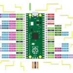
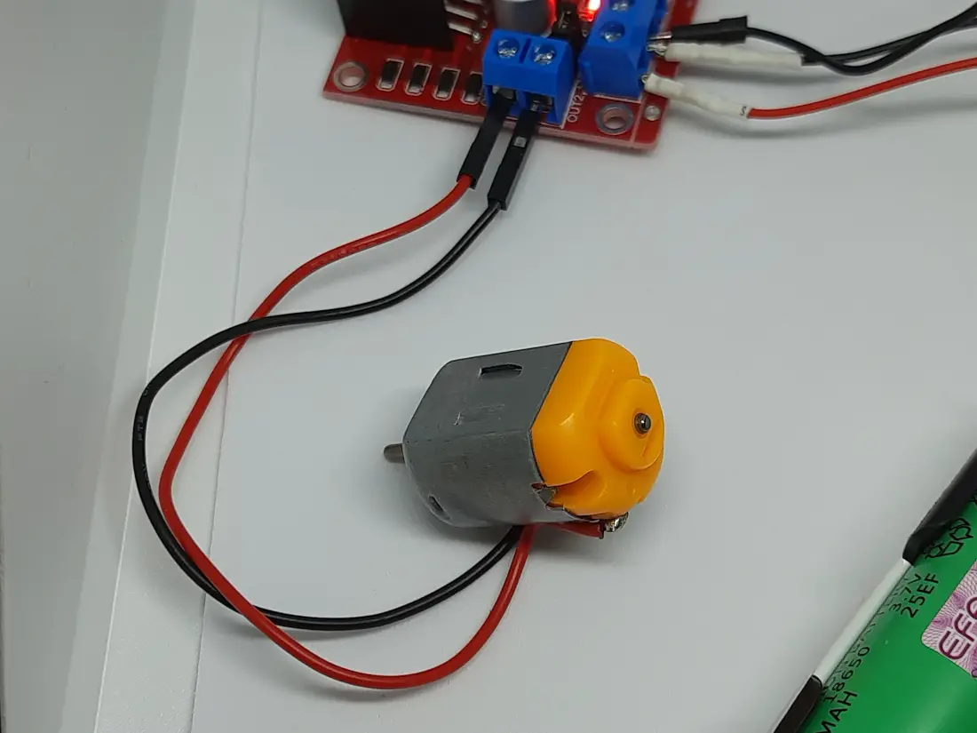
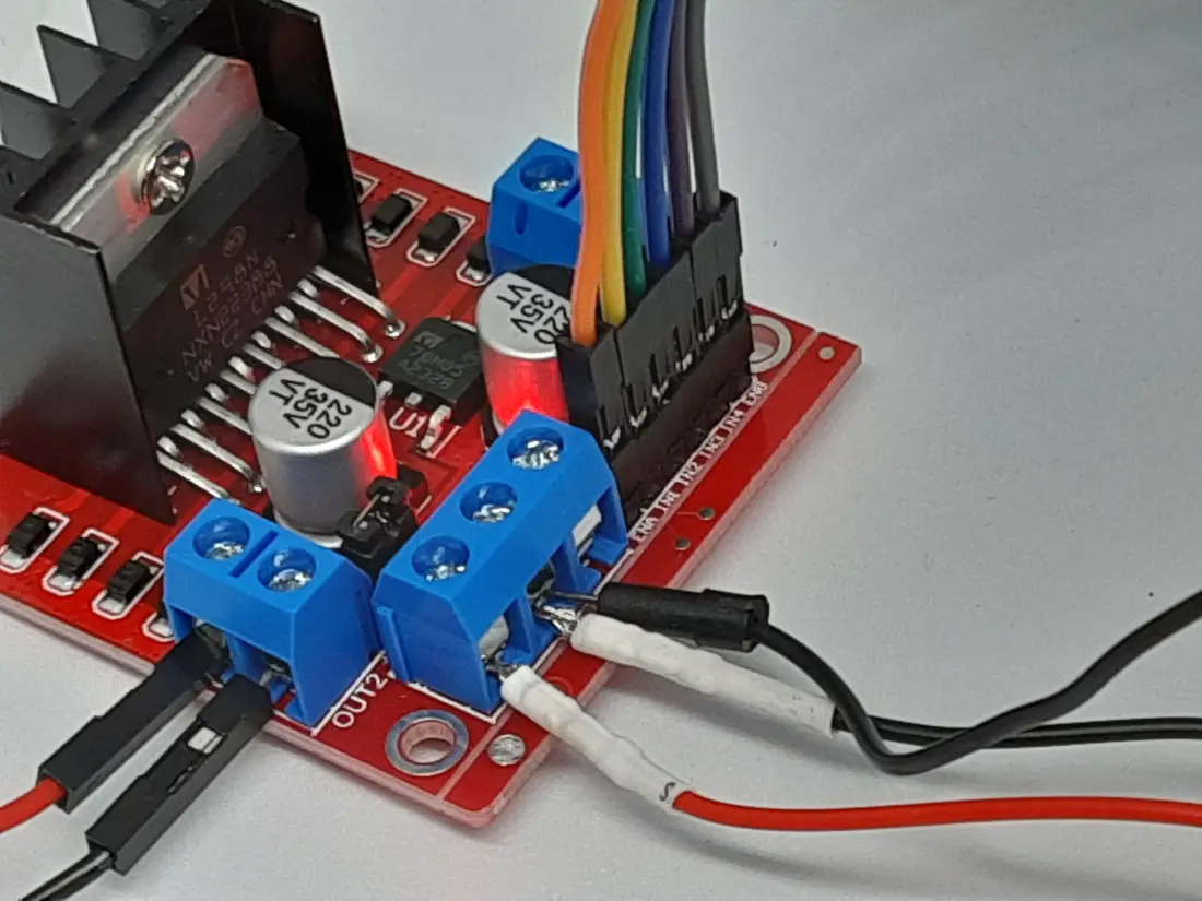
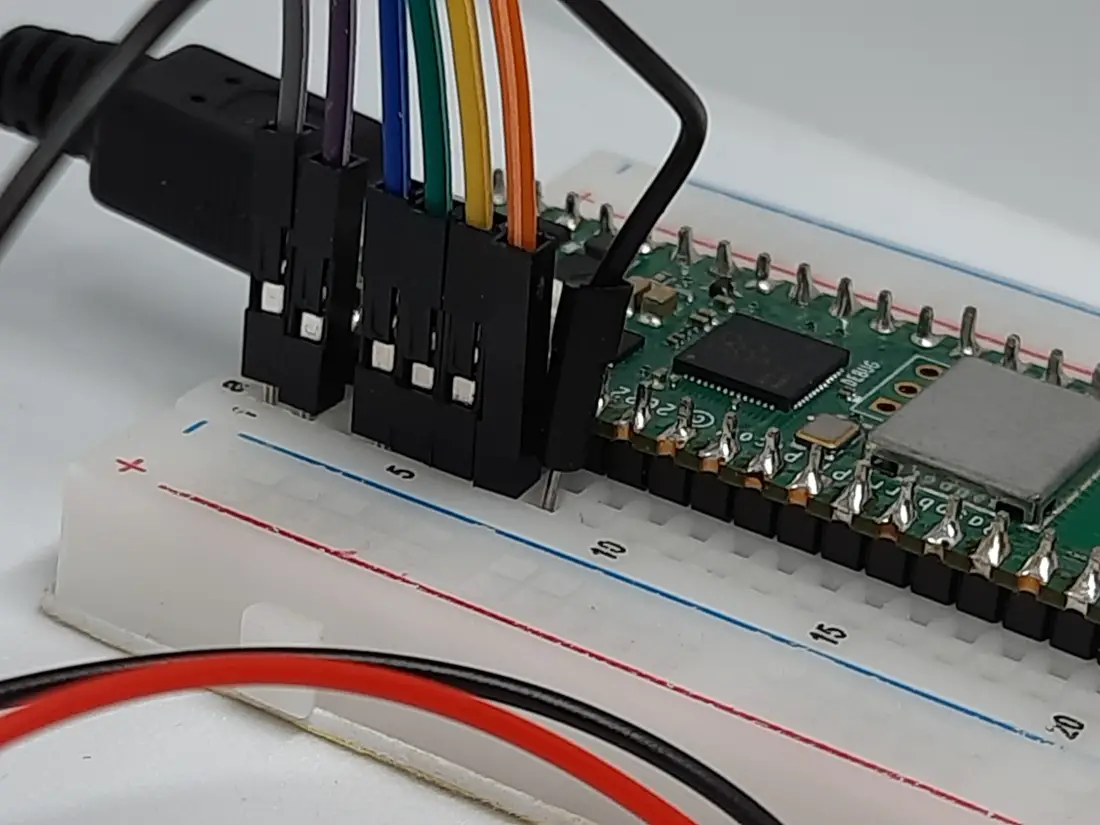
Please arrange the wirings as shown in the following picture, according to the Raspberry PI Pico Pinout. For this example, I will use 2x 18650 batteries as a power source. As they can provide around 3.7V for each one, this will make my test lab powered by a reliable 7.4 volts:
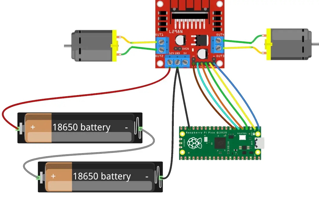
Please note that I’ve connected one of the Raspberry PI Pico GND PINs to the L298N GND PIN. This will allow our project to have a common ground signal. Moreover, while programming your Raspberry PI Pico via USB don’t connect the 5V out of L298N module with your Raspberry PI Pico.
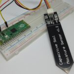
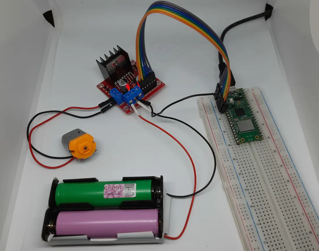
Please find below some pictures from my home lab, where I connected only 1 motor for the sake of simplicity:
Install MicroPython on Raspberry PI Pico
Connect RPI Pico to Thonny. For the very first steps and to install MicroPython, you can refer to my tutorial about the First steps with Raspberry PI Pico.
Get the L298N Library and Test Files
Download the library from my download area with the following link:
Please put this file in your Raspberry PI Pico storage, in the root folder (or any lib folder as explained in my Adding external modules to MicroPython with Raspberry PI Pico article).
Also, please download the following test file:
The following paragraphs will describe my code line by line. In the end, you will find the script’s expected results.
The test file to use l298N with Raspberry PI Pico
The test file will be so simple because the main job is done in my L298N library.
In the beginning, we import the required files:
from machine import Pin
from time import sleep
from l298n_lib import L298N_motor
The “L298N_motor” is an object taking as input 6 variables: the ENA, IN1, IN2, ENB, IN3, and IN4 (in this order). It expects as input the number of the Raspberry PI Pico PINs connected to these L298N ports.
For this reason, we’ll associate the L298N ports to 6 variables, so that it will be easier to read the code and change it if you need to use different ports:
ENB = 0
IN4 = 1
IN3 = 2

IN2 = 3
IN1 = 4
ENA = 5
So, we’ll initialize our L298N object with the following line:
motors = L298N_motor(ENA,IN1,IN2,ENB,IN3,IN4)The new object will have only 2 properties: “setSpeed” and “close”. The “setSpeed” property will set your motors speed according to the input number. This speed input will be a number between -100 and 100 (consider it as a percentage). Positive numbers will result in the motor rotating in a direction, while negative numbers will result in rotating in the opposite direction.
The setSpeed propriety will also allow you to manage both the motors’ speed (Group A and Group B) with one command line, as shown with the following command from our test code, where the print() statements have only the function to give you a notice about the speed you’re going to set in your shell:
print("Setting speed to 60%")
motors.setSpeed(60,0)
In this case, I’ve set the speed of motor A to 60% and left the motor B to 0 (zero -> OFF).
The following sleep() command will make the motor continue rotating for 2 seconds, while the setSpeed(0,0) will put to OFF both the motors:
sleep(2)
print("Setting speed to 0%")
motors.setSpeed(0,0)
Finally, the “close” property will release the PWM resources (used to set the motors speed in my library), so that you can correctly close your MicroPython code:
print("Closing...")
motors.close()
Running the l298-test.py Script
Run this script in your Thonny IDE (F5) and your motor will start rotating at 60% of its capacity:
>>> %Run -c $EDITOR_CONTENT
Setting speed to 60%
After 2 seconds, the speed will be set to 0, with the motor stopping:
Setting speed to 0%and, finally, the script will close, releasing all the PWM resources:
Closing...What’s Next
Interested in doing more with your Raspberry PI Pico? Try to look at my Raspberry PI Pico tutorials for useful and funny projects!
Enjoy!

Open source and Raspberry PI lover, writes tutorials for beginners since 2019. He's an ICT expert, with a strong experience in supporting medium to big companies and public administrations to manage their ICT infrastructures. He's supporting the Italian public administration in digital transformation projects.
![]()
![]()
![]()
![]()
![]()
![]()
![]()